Getting Started with MistySOM
MistySOM
Table Of Contents
- Getting Started with MistySOM
Getting Started with MistySOM
Introduction
This guide gets you started and set up to develop software and/or firmware for MistySOM.
MistyWest provides an environment in a docker container to build the BSP1 and an SDK2 for both versions of MistySOM. The host computer requires docker to be configured, set up and running. The requirements for setting up the host computer are described in the section Setting Up Host Computer.
Dependencies
The following instructions have some dependencies, they include:
- A running Linux host
- Installed
docker, runningdockerd(docker daemon) and added the current user to thedockergroup to allow execution of docker commands
Why Build Using Docker
Each version of Yocto may have unique Host requirements (e.g., Ubuntu 16.04, Ubuntu 18.04). This can be cumbersome during development if you are working on multiple projects at the same time. Dedicated build machines seem unfeasible for multiple reasons, one of which is the cost of hardware. Virtual machines have definite shortcomings as they reserve and virtualize the host hardware and only provide a limited set of resources to the build process.
Docker is a great solution to this problem and provides:
- Lightweight and simple to share configuration and setup files (allows the creation of identical environments)
- A git revision controlled build environment
- Flexible allocation of RAM and hard drive memory
- Little CPU/IO overhead (build time is not impacted)
- Containers that start and stop within 2 seconds
- The ability to run multiple containers simultaneously
- A build environment that is kept isolated from the host machine
Docker's efficiency allows multiple containers to be run simultaneously without burdening the host OS.
Setting Up Host Computer
A Linux host with a running docker daemon is required for building the MistySOM BSP and SDK. Docker can be installed through a distribution’s packaging manager. Look up how to install docker and start dockerd for your respective distributions. Some links to find documentation about some common distributions are listed below:
Ubuntu
https://docs.docker.com/engine/install/ubuntu/
Debian
https://docs.docker.com/engine/install/debian/
Fedora
https://docs.docker.com/engine/install/fedora/
Arch
https://docs.docker.com/desktop/install/archlinux/
After docker has been installed and started, you can confirm the functionality of the installation with the command:
$ docker run hello-world
If you see:
Hello from Docker!
it means your installation is working correctly.
Container Usage
Building and Starting the Container
The first step is to clone the MistySOM/rzv2l or MistySOM/rzg2l repository from GitHub3 using the commands:
$ git clone git@github.com:MistySOM/rzg2l.git
or
$ git clone git@github.com:MistySOM/rzv2l.git
make sure you have the latest submodules:
$ git submodule update --init --recursive
then enter the Build/ directory.
$ cd Build/
and execute
$ ./build.sh
This will download the required files and build the container. To enable caching, create a directory to cache the source packages and object build files. This directory can be reused for every subsequent container run, so that the files do not need to be downloaded and built multiple times. In the example below, that directory is called /path/to/dir/
Important: the directory needs to have read and write access for uid 1000 and gid 1000
(hint: you can execute chmod -R 777 /path/to/dir to grant read, write & execute access for the directory to everybody on your system )
The owner's uid and gid settings can be confirmed with
$ ls -na /path/to/dir
Which should provide a line similar to the one below if the first user on a Linux system was used to create the directory:
drwxr-xr-x 1 1000 1000 0 Month # HH:MM ./
If uid and gid do not indicate 1000 1000, please read about file permissions and attributes, see here.
Invoke the container and pass the cache directory with the command:
$ ./run.sh -c /path/to/dir
Upon completion of the build, the created image files are copied to the directory output/. This directory got created in the same path as where ./run.sh was invoked from. The rootfs, kernel, and device tree blob can now be copied to the destination uSD card. See section Output below.
Building the SDK
For development purposes, the SDK can be built with the above container. To do this, append the -s flag to the ./run.sh call:
$ ./run.sh -c /path/to/dir -s
This will automatically build the BSP and the SDK and copy the resulting files into the output/deploy/sdk/ directory.
Installation of the SDK
To install the SDK, execute it as user root on the host, e.g. with sudo as shown in the command below
(Note that /path/to/ is the location of your extracted MistySOMContainer archive)
$ sudo /path/to/out/deploy/sdk/poky-glibc-x86_64-core-image-<image_type>- aarch64-<board_name>-toolchain-3.1.5.sh
Upon which, paths can be set up by executing:
$ source /opt/poky/3.1.5/environment-setup-aatch64-poky-linux
This command has to be invoked every time before the SDK is used.
Description of Advanced Container Options
Building the BSP
- The script
run.shcan be supplied with an external path to a directory with-c /path/to/diror--cpath /path/to/dirwhere the Yocto downloads and the built object files can be cached (it requires about 10GB of empty space as of 10/20/2022) so that they do not need to be re-downloaded and re-built for every container run (just resubmit the same directory path). To allow the container to cache the data, the target directory needs to be writable by uid and gid 1000 (which is the default user id & group id of the first user on a Linux system, confirm withid -u,id -g&ln -n). - When no download path is submitted, the container will build the binaries in offline mode, utilizing the data & files that have been downloaded during the container build.
Building the SDK
The run.sh script, in addition, can be started with the argument -s to trigger the compilation of the SDK after the initial BSP build has finished. The SDK must not be built by itself, hence the -s switch will automatically build the BSP, followed by the SDK.
| Arg | Description |
-c --cpath DIRECTORY
|
Path to download cache directory |
-n --no
|
Container will start and environment will be setup. No build will be auto issued but a dev shell will start. |
-s --sdk
|
Container will build the SDK |
Output
After the compilation finishes, the shell in the container will remain active. The output is available in
- images/BSP:
/home/yocto/rzv_vlp_v3.0.0/out/deploy/images/[board]/ - SDK:
/home/yocto/rzv_vlp_v3.0.0/out/deploy/sdk/
The files in the above images/ directory include:
| Description | Filename |
| Linux kernel | Image-smarc-rzv2l.bin
|
| Device tree blob | r9a07g044l2-smarc.dtb
|
| Root filesystem | <image-name>-smarc-rzv2l.tar.bz2
|
| Partitioned image | <image-name>-smarc-rzv2l.wic.bz2
|
| Boot Loader | bl2_bp-smarc-rzv2l_pmic.srec & fip-smarc-rzv2l_pmic.srec
|
| FlashWriter | Flash_Writer_SCIF_RZV2L_SMARC_PMIC_DDR4_2GB_1PCS.mot
|
| SDK | poky-glibc-x86_64-core-image-<image_type>-aarch64-<board_name>-toolchain-3.1.5.sh
|
and the resources can simply be copied to the host with docker cp NAME:SRC DST where NAME is the name of the running container that can be retrieved by running docker ps on the host.
In order to test the newly built BSP, files need to be loaded to a uSD card that MistySOM will boot from. Please follow the instructions on the Preparing uSD card page accordingly.
Run time information
./build.shBuilds the container image from the Dockerfile and downloads the required files from the web../run.shWill start the container image, upon start, theexec.shscript is executed from within the containerexec.shinvokesstart.shwhich sets up the Yocto build environment inside the container- after the environment has been set up,
exec.shwill invoke the bitbake4 commands required to build the binary files
Develop Example Application
Hello World
Source Files
Create a file called helloworld.c with the following contents:
#include <stdio.h>

int main() {
	printf("Hello, World!\n");
	return 0;
}
Create a file called hello.bb5 that contains:
DESCRIPTION = "Simple helloworld application"
LICENSE = "MIT"
LIC_FILES_CHKSUM = "file://${COMMON_LICENSE_DIR}/MIT;md5=0835ade698e0bcf8506ecda2f7b4f302"

SRC_URI = "file://myhello.c"

S = "${WORKDIR}"

do_compile() {
	${CC} myhello.c ${LDFLAGS} -o myhello
}

do_install() {
	install -d ${D}${bindir}
	install -m 0755 myhello ${D}${bindir}
}
Build Using the Installed SDK
This step requires completion of the previous steps: Building the SDK and Installation of the SDK.
After the SDK has been installed, set the paths in your environment by executing:
$ sudo /path/to/out/deploy/sdk/poky-glibc-x86_64-core-image-<image_type>- aarch64-<board_name>-toolchain-3.1.5.sh
On your host computer.
$ $CC $CFLAGS $LDFLAGS helloworld.c -o helloworld
The resulting binary file helloworld can be copied and run on the MistySOM platform.
Build using Yocto
For testing this, the container should be started into a dev shell with:
./run.sh -n
or
./run.sh -c /path/to/dir -n
to launch it with the cache directory mounted.
Source the Build Environment
$ source poky/oe-init-build-env
and change to the directory where the layer is going to be located at
$ cd ..
Create Custom Layer
$ bitbake-layers create-layer --priority 3 meta-helloworld
Use the hello.c and hello.bb files from above to create the following directory structure within the meta-helloworld/ directory:
$ tree meta-helloworld
meta-helloworld
├── conf
│   └── layer.conf
├── COPYING.MIT
├── README
└── recipes-example
    ├── example
    │   └── example_0.1.bb
    └── myhello
        ├── files
        │   └── myhello.c
        └── myhello.bb
Add New Layer to Configuration
Execute the following command to add the line ${TOPDIR}/../meta-helloworld \ to the file conf/bblayers.conf (after the meta-renesas layer).
$ sed -i 's/renesas \\/&\n ${TOPDIR}\/..\/meta-helloworld \\/' conf/bblayers.conf
Build MyHello
By invocation of
$ bitbake myhello
The myhello test application will be built utilizing the bitbake server.
With
$ find . -name myhello*
The output package can be investigated.
To add the output of this recipe to the output images, add the following to your conf/local.conf file in your Yocto build directory:
IMAGE_INSTALL_append = " myhello"
This will put the myhello app to the rootfs.
MistySOM Development Shell
When the container gets started with the -n argument like:
./run.sh -n
The container image gets started with the Yocto build environment setup. For administrative tasks, the primary user in the container image is called yocto with the password set to yocto.
Configure U-Boot
In order for MistySOM to boot with the files copied onto the uSD card above, the bootloader needs to be configured accordingly. For instructions on how to configure U-Boot, please follow the information on Configure U-Boot
Connecting the Hardware
To test the build generated by following the instructions above, the MistySOM hardware has to be connected and powered up.
For development purposes, use the FTDI serial console cable6 and the UISB-C power cable7
Connect the FTDI able to connector J40 on MistyCarrier and connect the USB-C power cable to J1. The locations of the two connectors are highlighted in the following image:

Open a serial terminal: (instructions with tera Term for Windows or instructions with screen for Linux) and set the baudrate to 115200bps. If you connect the board successfully within the first few seconds of it booting, you should see boot messages followed by a login prompt:
smarc-rzg2l login:
If you don't see anything, press the Enter key and the above login prompt should appear. You can now log in with username root which will bring you to the shell from where you can invoke and execute commands.
Notes
BSP Board Support Package, also see: Board Support Package on Wikipedia
SDK Software Development Kit, also see Software Development Kit on Wikipedia
BitBake, also see BitBake
bb files are bitbake recipes, also see Recipes in BitBake User Manual
USB to TTL Serial Cable (3V3): type number: FTDI TTL-232R-3V3-2MM
USB-C power cable that is connected to a 5V/3A power brick
Preparing uSD Card Instructions
Important: Before doing anything, identify the correct uSD device
The following instructions are destructive and will clear the previously written data. So please ensure the device name you are using.
Identify the block device name for the SD Card with the command below. It is usually in the format of "/dev/sdX"
sudo fdisk -l
Use Partitioned Image
You can use the command below to write the whole partitioned image into your uSD card:
MistySOM-G2L
pv mistysom-image-smarc-rzg2l.wic.bz2 | bzcat | sudo dd bs=4M of=/dev/sdX
or if you don't have the pv package installed and you don't care about a progress bar, you can change the command like below:
bzcat mistysom-image-smarc-rzg2l.wic.bz2 | sudo dd bs=4M status=progress of=/dev/sdX
MistySOM-V2L
pv mistysom-image-smarc-rzv2l.wic.bz2 | bzcat | sudo dd bs=4M of=/dev/sdX
or if you don't have the pv package installed and you don't care about a progress bar, you can change the command like below:
bzcat mistysom-image-smarc-rzv2l.wic.bz2 | sudo dd bs=4M status=progress of=/dev/sdX
NOTE: For V2L and G2L, the above commands automatically create a partition table, 300 MB of FAT partition, and 900 MB of EXT4 partition. So it doesn't use the whole capacity of your uSD Card. If you need the whole capacity, you can resize the EXT4 partition with the command below:
resize2fs /dev/sdX2
If you are planning to use the eMMC storage, it is recommended to resize the partition after you have copied the partition to the eMMC storage.
Manual Approach
Partition and Format the uSD
The uSD card should be formatted with two partitions, FAT32 and EXT4. Parted provides a terminal utility to do this, alternatively gparted or another graphical partition editor can be used from the GUI.
- Install the tool (the example below applies to Ubuntu or Debian-based systems, use the package manager of your distribution accordingly)
sudo apt update
sudo apt install parted
- Identify the block device name for the SD Card, for example "/dev/sdc"
sudo fdisk -l
- Create the partition table with a FAT32 and an EXT4 partition
sudo parted /dev/sdc --script -- mklabel gpt
sudo parted /dev/sdc --script -- mkpart primary fat32 0% 30MiB
sudo parted /dev/sdc --script -- mkpart primary ext4 30MiB 100%
- Format the partitions to FAT32 and EXT4
sudo mkfs.fat -F 32  /dev/sdc1
sudo mkfs.ext4 -F /dev/sdc2
- Confirm the partition table is set as expected
sudo parted /dev/sdc --script print
Expected output:
Model: SD EB1QT (sd/mmc)
Disk /dev/sdc: 32.0GB
Sector size (logical/physical): 512B/512B
Partition Table: gpt
Disk Flags:

Number  Start   End     Size    File system  Name     Flags
 1      1049kB  31.5MB  30.4MB  fat32        primary  msftdata
 2      31.5MB  32.0GB  32.0GB  ext4         primary
Load files to the uSD card
After the uSD card has been prepared, mount the two partitions and copy the following files:
MistySOM-G2L
- Linux kernel to the first partition (FAT32):
sudo cp /path/to/output/imges/smarc-rzg2l/Image-smarc-rzg2l.bin /path/to/mountpart1/Image
- Device tree blob to the first partition (FAT32)
sudo cp /path/to/output/imges/smarc-rzg2l/r9a07g044l2-smarc.dtb /path/to/mountpart1/
- Root filesystem to the second partition (ext4)
sudo cp /path/to/output/imges/smarc-rzg2l/<image-name>-smarc-rzg2l.tar.bz2 /path/to/mountpart2/
cd /path/to/mountpart2/
tar -xvf <image-name>-smarc-rzv2l.tar.bz2
MistySOM-V2L
- Linux kernel to the first partition (FAT32):
sudo cp /path/to/output/imges/smarc-rzv2l/Image-smarc-rzv2l.bin /path/to/mountpart1/Image
- Device tree blob to the first partition (FAT32)
sudo cp /path/to/output/imges/smarc-rzv2l/r9a07g054l2-smarc.dtb /path/to/mountpart1/
- Root filesystem to the second partition (ext4)
sudo cp /path/to/output/imges/smarc-rzv2l/<image-name>-smarc-rzv2l.tar.bz2 /path/to/mountpart2/
cd /path/to/mountpart2/
tar -xvf <image-name>-smarc-rzv2l.tar.bz2
NOTE: For V2L and G2L, after this, your uSD card is ready to be inserted into the MistyCarrier uSD slot. In order to be able to boot from the SD card, please make sure that jumper J23 is set to the uSD (pins 1&2) position. Jumper J23 is located under the uSD card slot, a bit to the left as seen in the picture below and has two positions, uSD and WIRELESS: 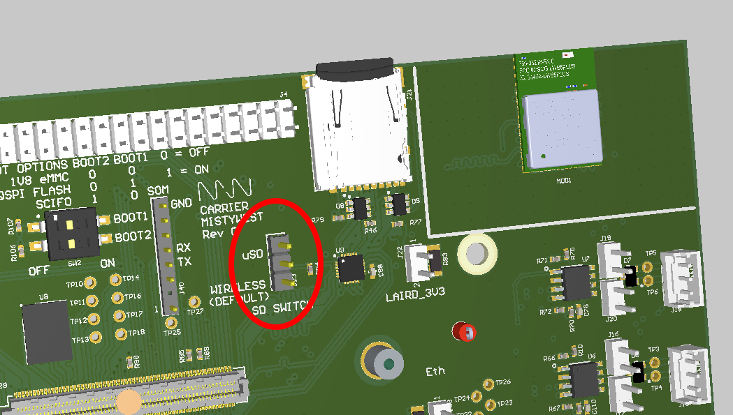
Note to WSL users:
Make sure to work with files on Linux mounts (avoid the use of mounted Windows partitions)
Program eMMC flash
- To program the eMMC Flash device on MistySOM, the below instructions can be followed.
- You will need to boot with an SD card first and partition the eMMC Flash device. Then you can load the files from the SD card to eMMC Flash.
-
Boot the board with the SD card and log into Linux.
-
Partition the eMMC Flash using fdisk.
In fdisk, use the commands 'n' to make a new partition, and 'w' to write the partition (will automatically exit fdisk) In fdisk, you can just press the Enter Key to select the default value (you do not have to type the default value)
root@smarc-rzg2l:~# fdisk /dev/mmcblk0 Command (m for help): n p primary (0 primary, 0 extended, 4 free) e extended (container for logical partitions) Select (default p): p <<<< just press ENTER for default value Partition number (1-128, default 1): 1 <<<< just press ENTER for default value First sector (34-124321758, default 2048): 2048 <<<< just press ENTER for default value Last sector, +/-sectors or +/-size{K,M,G,T,P} (2048-124321758, default 124321758): 124321758 <<<< just press ENTER for default value Created a new partition 1 of type 'Linux filesystem' and of size 59.3 GiB. Command (m for help): w The partition table has been altered. -
Copy the currently booted root partition to the newly created partition:
root@smarc-rzg2l:~# dd bs=4M status=progress if=/dev/mmcblk1p2 of=/dev/mmcblk0p1 root@smarc-rzg2l:~# resize2fs /dev/mmcblk0p1 root@smarc-rzg2l:~# sync -
Reboot and change the boot parameter in u-boot to boot from eMMC
RZG2L
=> setenv bootargs 'rw rootwait earlycon root=/dev/mmcblk0p1'
=> setenv bootcmd 'ext4load mmc 0:1 0x48080000 boot/Image-smarc-rzg2l.bin; ext4load mmc 0:1 0x48000000 boot/r9a07g044l2-smarc.dtb; booti 0x48080000 - 0x48000000'
=> saveenv
=> boot
RZV2L
=> setenv bootargs 'rw rootwait earlycon root=/dev/mmcblk0p1'
=> setenv bootcmd 'ext4load mmc 0:1 0x48080000 boot/Image; ext4load mmc 0:1 0x48000000 boot/r9a07g054l2-smarc.dtb; booti 0x48080000 - 0x48000000'
=> saveenv
=> boot
Board Start-Up Guide MistySOM
Requirements
- For Windows:
- TerasTerm (link to download)
- For Linux:
- root permissions (sudo)
- (use your distribution's package manager to install the following utilities):
- screen
- dd
- pv
Booting Flash Writer
-
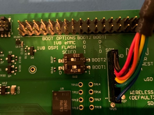
Set the boot mode to SCIF. On the MistySOM Carrier board, on SW2, set BOOT1 OFF and BOOT2 to ON.
-
Connect the
FTDI cabletoJ40on the MistyCarrier board and a USB port on the computer -
On Windows:
- Start TeraTerm and select the
COMn: USB Serial Port (COMn)interface. - Set the Baud rate under
Setup -> Serial Port... -> Speed:to115200and click theNew Settingbutton.
On Linux: Open a terminal and run the command:
sudo screen /dev/ttyUSB0 115200 - Start TeraTerm and select the
-
Power on the MistySOM board.
-
Upon application of power and turning the unit on with the
PWR_ONswitch, you should see the following on your terminal window:(C) Renesas Electronics Corp. -- Load Program to SystemRAM --------------- please send ! -
Download and save the file
Flash_Writer_SCIF__.mot(MistySOM-G2L or MistySOM-V2L) by clicking on Raw button and then using Save as over the opened content. -
In TeraTerm (on Windows): Select
File -> Send File...and select the fileFlash_Writer_SCIF__.mot. A transfer dialog will appear displaying the progress of the file transfer over the serial connection.
On Linux: Open another terminal window and run the command:pv Flash_Writer_SCIF__.mot | sudo dd of=/dev/ttyUSB0
After successful downloading of the binary, Flash Writer starts automatically and shows a message like the one shown below on the terminal
Flash writer for RZ/V2 Series V1.02 Nov.15,2021
 Product Code : RZ/V2L
>
Writing Bootloader
For the boot operation, two boot loader files need to be written to the target board.
Type XLS2 and confirm with [ENTER]:
Enter the top address 11E00
and the Qspi address 00000:
>XLS2
===== Qspi writing of RZ/G2 Board Command =============
Load Program to Spiflash
Writes to any of SPI address.
Micron : MT25QU512
Program Top Address & Qspi Save Address
===== Please Input Program Top Address ============
Please Input : H'11E00
===== Please Input Qspi Save Address ===
Please Input : H'00000
Work RAM(H'50000000-H'53FFFFFF) Clear....
please send ! ('.' & CR stop load)
Send the data of “bl2_bp-MistySOMG2L.srec” (download for MistySOM-G2L or MistySOM-V2L) from terminal software after the message “please send !” is shown.
After the successful download of the binary, messages like below are shown on the terminal.
SPI Data Clear(H'FF) Check :H'00000000-0000FFFF Erasing..Erase Completed
SAVE SPI-FLASH.......
======= Qspi Save Information =================
SpiFlashMemory Stat Address : H'00000000
SpiFlashMemory End Address : H'00009A80
===========================================================

SPI Data Clear(H'FF) Check : H'00000000-0000FFFF,Clear OK?(y/n)
In case a message prompt to clear data like the above appears, please enter “y”.
Next, write another loader file by using the XLS2 command again.
With top address 00000
and Qspi address 1D200:
>XLS2
===== Qspi writing of RZ/G2 Board Command =============
Load Program to Spiflash
Writes to any of SPI address.
Micron : MT25QU512
Program Top Address & Qspi Save Address
===== Please Input Program Top Address ============
Please Input : H'00000
===== Please Input Qspi Save Address ===
Please Input : H'1D200
Work RAM(H'50000000-H'53FFFFFF) Clear....
please send ! ('.' & CR stop load)
Send the data of “fip-MistySOMG2L.srec”(download for MistySOM-G2L or MistySOM-V2L) from terminal software after the message “please send !” is shown.
After the successful download of the binary, messages like below are shown on the terminal.
SPI Data Clear(H'FF) Check :H'00000000-0000FFFF Erasing..Erase Completed
SAVE SPI-FLASH.......
======= Qspi Save Information =================
SpiFlashMemory Stat Address : H'0001D200
SpiFlashMemory End Address : H'000CC73F

SPI Data Clear(H'FF) Check : H'00000000-0000FFFF,Clear OK?(y/n)
In case a message to prompt to clear data like the above appears, please enter “y”.
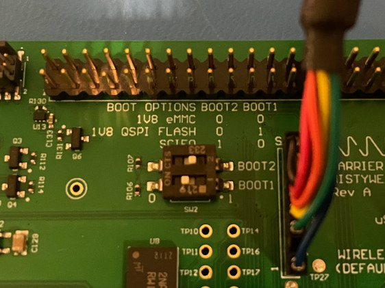
After writing two loader files normally, pull the power cable to the board and set SW2 into QSPI boot mode:
-
BOOT1 ON
-
BOOT2 OFF
Configure U-Boot
Reapply power to the board and turn it on with the PWR_ON switch.
The following will appear on the terminal::
þÿNOTICE:  BL2: v2.5(release):v2.5/rzg2l-1.00-49-g7b68034f7
NOTICE:  BL2: Built : 18:44:43, Dec  7 2022
NOTICE:  BL2: Booting BL31
NOTICE:  BL31: v2.5(release):v2.5/rzg2l-1.00-49-g7b68034f7
NOTICE:  BL31: Built : 18:44:43, Dec  7 2022


U-Boot 2021.10-g8a08fc7390 (Dec 07 2022 - 10:44:16 -0800)

CPU:   Renesas Electronics K rev 16.15
Model: smarc-rzg2l
DRAM:  1.9 GiB
MMC:   sd@11c00000: 0, sd@11c10000: 1
Loading Environment from MMC... *** Warning - bad CRC, using default environment

In:    serial@1004b800
Out:   serial@1004b800
Err:   serial@1004b800
Net:   No ethernet found.

Hit any key to stop autoboot:  0
## Resetting to default environment
Card did not respond to voltage select! : -110
** No partition table - mmc 0 **
Couldn't find partition mmc 0:1
Can't set block device
** No partition table - mmc 0 **
Couldn't find partition mmc 0:1
Can't set block device
Error: Bad gzipped data
Bad Linux ARM64 Image magic!
=>
the bottom prompt => indicates the U-Boot prompt.
Enter
=> env default -a
## Resetting to default environment
=> saveenv
Saving Environment to MMC... Writing to MMC(0)....OK
=>
to reset the values to a defined default state, ready for custom configuration.
After the SDcard has been prepared and inserted, set the boot variables on the U-boot prompt with:
For MistySOM-G2L:
=> setenv bootcmd 'mmc dev 1;fatload mmc 1:1 0x48080000 Image;fatload mmc 1:1 0x48000000 r9a07g044l2-smarc.dtb; booti 0x48080000 - 0x48000000'
=> setenv bootargs 'root=/dev/mmcblk1p2 rootwait'
For MistySOM_V2L:
=> setenv bootcmd 'mmc dev 1;fatload mmc 1:1 0x48080000 Image;fatload mmc 1:1 0x48000000 r9a07g054l2-smarc.dtb; booti 0x48080000 - 0x48000000'
=> setenv bootargs 'root=/dev/mmcblk1p2 rootwait'
Confirm with
=> saveenv
power cycle the board and it should now boot up to a Linux prompt where you can log in with root
Poky (Yocto Project Reference Distro) 3.1.14 smarc-rzg2l ttySC0

smarc-rzg2l login: root
Camera Selection
MistySOM is currently supporting different cameras. They require a different device-tree file to be configured on the U-Boot. All different device-tree files and kernel modules are included inside the boot directory of the MistySOM image.
The following is the list of supported cameras and their related device-tree:
-
Coral Camera
A 5-megapixel camera module that's compatible with the Coral Dev Board and Dev Board Mini. Connects through the MIPI-CSI interface, and provides an easy way to bring visual inputs. Read more here
- RZG2L Device-Tree: r9a07g044l2-smarc.dtb
- RZV2L Device-Tree: r9a07g054l2-smarc.dtb
-
e-CAM20_CURZ - AR0234 Global Shutter Camera
A 2-megapixel custom lens camera module based on 1/2.6" AR0234CS CMOS image sensor from ON Semiconductor®. It is a color camera which supports UYVY image format and provided with S-mount (also known as M12 board lens) lens holder. Read more here
- RZG2L Device-Tree: r9a07g044l2-smarc-ar0234.dtb
- RZV2L Device-Tree: r9a07g054l2-smarc-ar0234.dtb
-
e-CAM221_CUMI462_MOD - Sony® Starvis™ IMX462 Ultra-Lowlight Camera Module
It is based on a SONY® STARVIS™ IMX462LQR sensor that ensures superior near-infrared performance. The high sensitivity of this Full HD camera module helps to capture images in as extremely low lighting conditions as 0 lux, which makes it suitable for night vision applications and medical microscopes. Read more here
- RZG2L Device-Tree: r9a07g044l2-smarc-imx462.dtb
- RZV2L Device-Tree: r9a07g054l2-smarc-imx462.dtb
Build Bootloaders
Revision History
| Version | Description of Changes | Date |
| 1.0 | Initial Version | 12/08/2022 |
Introduction
In order to boot MistySOM into Linux, it requires to be loaded with bootloaders.
Dependencies
The bootloaders are set to be built on a Linux machine. Dependencies include the following packages (on Ubuntu distributions, installation of the `build-essentials package will resolve all dependencies):
- installed SDK (see the Getting Started Guide on information about how to build and install the SDK)
- installed git package
- installed make package
The bootloaders are separate per SOM basis, as documented below:
MistySOMG2L
Clone Source Code
Change directories to a location from where the source code can be built
$ git clone git@github.com:MistySOM/rzg2_bsp_scripts.git
$ git checkout MistySOMG2L
$ git submodule update --init --recursive
$ cd build_scripts/
MistySOMV2L
Clone Source Code
Change directories to a location from where the source code can be built
$ git clone git@github.com:MistySOM/rzg2_bsp_scripts.git
$ git checkout MistySOMV2L
$ git submodule update --init --recursive
$ cd build_scripts/
Helpful U-Boot Commands
Revision History
| Version | Description of Changes | Date |
| 1.0 | Initial Version | 12/07/2022 |
SDCard & MMC commands
Confirm SDcard Contents
=> mmc list
sd@11c00000: 0 (eMMC)
sd@11c10000: 1
Select Device
=> mmc dev 1
switch to partitions #0, OK
mmc1 is current device
List Partitions
=> mmc part

Partition Map for MMC device 1  --   Partition Type: DOS

Part    Start Sector    Num Sectors     UUID            Type
  1     2048            67584           a1d1165e-01     0b
  2     69632           62451712        a1d1165e-02     83
List Files on Partition (fatls for fat, ext4ls for ext4 partitions)
=> fatls mmc 1:1
 16955904   Image
    37530   r9a07g044l2-smarc.dtb

2 file(s), 0 dir(s)
Restore Default Configuration
env default -a
Variables that need to be Updated to Boot MistySOM
bootargs
bootcmd
Connect In-Circuit Debugger
Revision History
| Version | Description of Changes | Date |
| 1.0 | Initial Version | 12/12/2022 |
Requirements
Software
GDB
You need to have built the SDK by following the Getting Started Guide. If you installed the SDK at the default location in /opt/poky, we need the gdb binary from:
/opt/poky/3.1.14/sysroots/x86_64-pokysdk-linux/usr/bin/arm-poky-linux/arm-poky-linux-gdb
OpenOCD
To build OpenOCD you can use this script, e.g.:
$ wget https://raw.githubusercontent.com/renesas-rz/rzg_openocd/master/build_openocd
$ chmod +x build_openocd
$ ./build_openocd
Connect to the Board
Settings
Power cycle the MistyCarrier board, with both switches, 1 & 2 on SW1 in the OFF position.
OpenOCD
Start OpenOCD with the following command:
$ sudo bin/openocd -f share/openocd/scripts/interface/jlink.cfg -c "set SOC G2L" -f share/openocd/scripts/target/renesas_rz_g2.cfg
and you expect it to start with the following message:
Info : JTAG tap: r9a07g044l.cpu tap/device found: 0x6ba00477 (mfg: 0x23b (ARM Ltd), part: 0xba00, ver: 0x6)
Info : r9a07g044l.a55.0: hardware has 6 breakpoints, 4 watchpoints
Info : starting gdb server for r9a07g044l.a55.0 on 3333
Info : Listening on port 3333 for gdb connections
Info : starting gdb server for r9a07g044l.m33 on 3334
Info : Listening on port 3334 for gdb connections
Info : gdb port disabled
After it has started as seen above, open a new terminal window to launch the gdb binary indicated above under Requirements.
In the new window launch gdb from the installed SDK:
$ /opt/poky/3.1.14/sysroots/x86_64-pokysdk-linux/usr/bin/aarch64-poky-linux/aarch64-poky-linux-gdb Flash_Writer_SCIF_RZV2L_SMARC_PMIC_DDR4_2GB_1PCS.mot
with the Flash_Writer binary that was compiled following the instructions about building the bootloaders.
Upon execution of the above command, a screen similar to the below is expected:
GNU gdb (GDB) 9.1
Copyright (C) 2020 Free Software Foundation, Inc.
License GPLv3+: GNU GPL version 3 or later <http://gnu.org/licenses/gpl.html>
This is free software: you are free to change and redistribute it.
There is NO WARRANTY, to the extent permitted by law.
Type "show copying" and "show warranty" for details.
This GDB was configured as "--host=x86_64-pokysdk-linux --target=aarch64-poky-linux".
Type "show configuration" for configuration details.
For bug reporting instructions, please see:
<http://www.gnu.org/software/gdb/bugs/>.
Find the GDB manual and other documentation resources online at:
    <http://www.gnu.org/software/gdb/documentation/>.

For help, type "help".
Type "apropos word" to search for commands related to "word"...
Reading symbols from Flash_Writer_SCIF_RZV2L_SMARC_PMIC_DDR4_2GB_1PCS.mot...
(No debugging symbols found in Flash_Writer_SCIF_RZV2L_SMARC_PMIC_DDR4_2GB_1PCS.mot)
upon which a connection to the remote target can be established by entering:
(gdb) target remote localhost:3333
this should be acknowledged in the other window where openocd was started with
Info : accepting 'gdb' connection on tcp/3333
Info : New GDB Connection: 1, Target r9a07g044l.a55.0, state: halted
entering the command
gdb) monitor reset init
will reset the MPU which can be confirmed by watching the output on the serial console.
Follow info on Z-G/RZG2 Eclipse develop and debug to setup Eclipse with OCD for debugging Flash Writer.
Starting SSH
Revision History
| Version | Description of Changes | Date |
| 1.0 | Initial Version | 12/27/2022 |
Start SSH Server
To enable the ssh daemon, log in with the serial terminal and enter:
# systemctl start sshd
Autostart SSH Server on Reboot
To start the ssh server automatically after subsequent reboots, enter:
# systemctl enable sshd
Allow Clients to Connect Using RSA
Some ssh clients need to be configured explicitly to allow to connect with rsa encryption. To do so, create a file ~/.ssh/config and add the following contents:
Host 192.168.1.15
    User git
    PubkeyAcceptedAlgorithms +ssh-rsa
    HostkeyAlgorithms +ssh-rsa
Where the IP address following Host has to be the same as the one that MistySOM leased from your DHCP server. To find the address on MistySOM, type # ip a and look for the address listed under the interface eth2:
Streaming Video
For streaming a live video feed from the camera, you need to be connected to a network using Ethernet or WiFi (see here) and know the IP address of the destination computer.
Stream Listener
The destination computer should be listening to an incoming video on a port (in this example port 51372)
To set up the listening, you have different options:
GStreamer
Use the command below:
$ gst-launch-1.0 -v udpsrc port=51372 \
    caps="application/x-rtp, media=video, clock-rate=90000, encoding-name=H264, payload=96" \
    ! rtph264depay ! decodebin ! videoconvert \
    ! autovideosink
- Note: In case you want to see the number of frames it receives per second, you can replace the
autovideosinkin the last line with:fpsdisplaysink text-overlay=0 video-sink=autovideosink
VLC or FFmpeg
Create an SDP (in this example stream.sdp) file with the contents below:
v=0
o=- 0 0 IN IP4 0.0.0.0/32
s=ESP H264 STREAM
i=MistySOM
c=IN IP4 0.0.0.0/32
t=0 0
m=video 51372 RTP/AVP 96
a=rtpmap:96 H264/90000
Then you open this file by double-clicking or command lines below:
$ vlc stream.sdp
$ ffplay -protocol_whitelist file,crypt,udp,rtp stream.sdp
-
Note: In case you need no delay when using
ffplay, you can add the following arguments to the command:-fflags nobuffer -flags low_delay -framedrop -strict experimental -
Note: In case you need no delay when using VLC: TBD
Stream Sender (MistySOM)
First, make sure you have the modules below loaded in the kernel with the command below:
$ lsmod
Module                  Size  Used by
vspm_if                49152  0
vspm                  102400  1 vspm_if
uvcs_drv               40960  0
mmngrbuf               16384  0
mmngr                  24576  0
Second, make sure you have an active IP address network connection with the command below:
$ ip a | grep inet
    inet 127.0.0.1/8 scope host lo
    inet 192.168.100.154/24 brd 192.168.100.255 scope global dynamic wlan0
Then, you can send a video stream with GStreamer. Because the command is very long and it makes editing difficult, we recommend that you create a stream.sh bash file in your home directory (alongside the file v4l2-init.sh) with the following contents:
#!/bin/bash
[ $1 ] || { echo  "Please specify the destination IP address: ./stream.sh ip [width] [height]" >&2; exit 1; }
W="${2:-1920}"
H="${3:-1080}"

./v4l2-init.sh
echo "Streaming to ${1} with resolution ${W}x${H}..."

gst-launch-1.0 v4l2src device=/dev/video0 ! video/x-raw, width=1920, height=1080 \
	! vspmfilter dmabuf-use=true ! video/x-raw,format=NV12,width=$W,height=$H \
	! omxh264enc control-rate=2 target-bitrate=10485760 interval_intraframes=14 periodicty-idr=2 \
	! video/x-h264,profile=\(string\)high,level=\(string\)4.2 \
	! rtph264pay config-interval=-1 ! udpsink host=$1 port=51372
- Note: Remember to make the file executable using
chmod +x stream.sh
Then start the stream to the listener computer (in this example with IP address of 192.168.100.132) with your desired resolution (in this example 640x360) with the command below:
$ ./stream.sh 192.168.100.132 640 360
Convert an existing model to MistySOM V2L
DRP-AI TVM Makes It Easy to Port AI Model into RZ/V Devices
Have you ever found it difficult to implement an AI model in an embedded device? I would like to introduce DRP-AI TVM1 for easy porting of AI models.
In recent years, the implementation of AI in embedded devices such as surveillance cameras, traffic monitoring systems, robots, and drones has been increasing. Unlike the cloud environment, embedded devices have many considerations such as HW performance and restrictions in cost and power consumption, making AI implementation difficult. By using the AI-MPU RZ/V series, which implements Renesas' low-power AI accelerator DRP-AI, most of the hardware implementation issues can be resolved.
When users implement AI models into MPUs, they can use the DRP-AI translator to convert AI models into DRP-AI executable format. However, we received feedback from some users about the difficulty of implementation.
The main reasons are two.
- AI model format supported by the DRP-AI translator is ONNX only.
- If non-supported AI model operators are included in AI models, the DRP-AI translator cannot convert it into an executable format.
Renesas has asked users to handle such cases themselves, which has caused a burden on some users. Edgecortix2 released DRP-AI TVM to solve the issues and to improve user experience.
DRP-AI TVM is the tool that added DRP-AI support on an open-source ML compiler Apache TVM3. Using DRP-AI TVM, AI model operators non-supported by DRP-AI translator can be automatically allocated to CPUs to implement more AI models into RZ/V products easily. DRP-AI TVM supports not only ONNX, and other AI frameworks such as Poarch and TensorFlow, etc.
Furthermore, as with the conventional DRP-AI translator flow, DRP-AI can handle the pre-processing of AI inference, enabling total AI performance improvement, including pre-processing.
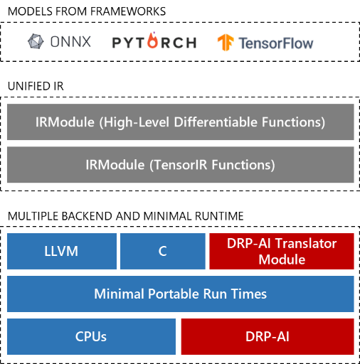
DRP-AI TVM structure
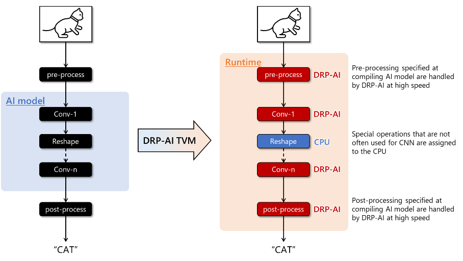
Auto AI model operators’ allocation by DRP-AI TVM
DRP-AI TVM is public on GitHub for users to ease access. Users can find sufficient information to use DRP-AI TVM on GitHub, such as the tutorial, sample code, and a variety of AI model performances. The tutorial includes steps from building the environment to AI inference on an evaluation board, and customers can use these steps to evaluate their AI models easily. Renesas will continue to strive for UX improvements to make it easier for customers to use Renesas products.
DRP-AI TVM is powered by Edgecortix MERATM Compiler Framework
EdgeCortix MERA
RZ/V series introduction
Renesas info wiki RZ/V series
DRP-AI introduction
DRP-AI TVM GitHub
DRP-AI TVM Tutorial
source: DRP-AI TVM Makes It Easy to Port AI Model into RZ/V Devices
Convert from Tensorflow
hosted on tvm.apache.org:
Video Inference with DRPAI and GStreamer
MistySOM RZV2L contains the DRPAI hardware module which is able to run artificial Neural Networks
with the focus on low power consumption. To check if this hardware module is present on your device,
you can look for both /dev/drpai0 and /dev/udmabuf0 devices on your Linux shell.
The Userland Direct Memory Access (UDMA) kernel module is required to provide the trained AI model and
the input image to the DRPAI hardware. After activating the hardware, it will use the trained model to
generate the output which can be read by the UDMA module. While DRPAI is running, the running thread will
go to sleep. Of course, the sleep time varies based on the size of the AI model.
MistyWest team has prepared a GStreamer plugin for DRPAI which can receive any kind of video input, such as a file (filesrc), a network stream (udpsrc), or a camera device (v4l2src) and outputs a video with bounding boxes on inferred objects using the DRPAI. Later, this video can be linked to any kind of output, such as the display (autovideosink), a network stream (udpsink), or a file (filesink).

The plugin uses the following pad template capabilities for both src and sink which requires you
to prepare before your DRPAI element (for example, using a videoconvert element):
video/x-raw
    width: 640
    height: 480
    format: BGR
The plugin also provides you with the following parameters:
General Parameters
| Name | Type | Default | Description |
|---|---|---|---|
| model | String | --- | (Required) The name of the pre-trained model and the directory prefix. |
| multithread | Boolean | true | Use a separate thread for object detection. |
| log-detects | Boolean | false | Print detected objects in standard output. |
| log-server | Host:Port (String) | --- | Address of logs to send in UDP messages in JSON format to the specified port on a remote host. |
| show-fps | Boolean | false | Render frame rates of video and DRPAI at the corner of the video. |
| stop-error | Boolean | true | Stop the gstreamer if kernel modules fail to open. |
| max-video-rate | Float [0.001 - 120] | 120 | Force maximum video frame rate using thread sleeps. |
| max-drpai-rate | Float [0 - 120] | 120 | Force maximum DRPAI frame rate using thread sleeps. |
| smooth-video-rate | Float [1 - 1000] | 1 | Number of last video frame rates to average for a more smooth value. |
| smooth-drpai-rate | Float [1 - 1000] | 1 | Number of last DRPAI frame rates to average for a more smooth value. |
| smooth-bbox-rate | Float [1 - 1000] | 1 | Number of last bounding-box updates to average. (requires tracking) |
Tracking Parameters (YOLO specific)
| Name | Type | Default | Description |
|---|---|---|---|
| tracking | Boolean | true | Track detected objects based on their previous locations. Each detected object gets an ID that persists across multiple detections based on other tracking properties. |
| show-track-id | Boolean | false | Show the track ID on the detection labels. |
| track-seconds | Float [0.001 - 100] | 2 | Number of seconds to wait for a tracked undetected object to forget it. |
| track-doa-thresh | Float [0.001 - 1000] | 2.25 | The threshold of Distance Over Areas (DOA) for tracking bounding-boxes. |
| track-history-length | Integer [0 - 1440] | 60 | Minutes to keep the tracking history. |
Filtering Parameters (YOLO specific)
| Name | Type | Default | Description |
|---|---|---|---|
| filter-show | Boolean | false | Show a yellow box where the filter is applied. |
| filter-class | String | --- | A comma-separated list of classes to filter the detection. Shows all if empty. |
| filter-left | Integer [0 - 639] | 0 | The left edge of the region of interest to filter the detection. |
| filter-top | Integer [0 - 479] | 0 | The top edge of the region of interest to filter the detection. |
| filter-width | Integer [1 - 640] | 640 | The left edge of the region of interest to filter the detection. |
| filter-height | Integer [1 - 480] | 480 | The left edge of the region of interest to filter the detection. |
AI Model
The plugin is implemented in a way that it can run different models. By using the model parameter,
you can switch between different DRP-AI translated models that are located in a directory with
the same name as the model. For example, when using the parameter model=yolov3, and you are running
the command on your home directory /home/user, the plugin loads the TVM compiled model located in
/home/user/yolov3.
MistyWest has already placed compatible yolov2, yolov3, tinyyolov2, and tinyyolov3 models
for you to download from here and extract
into the desired location. For details on how the GStreamer plugin uses them, refer to the next sections.
Model Dynamic Library
Depending on the model you use, even though their input layers are the same, their output layers can be
very different and require additional post-processing to interpret the array of floating point numbers
to a data structure that is used to render the bounding boxes for each inferred object. Therefore,
the plugin uses a shared library that needs to be included with the model and its path is mentioned in
the {model}/{model}_process_params.txt file like this:
[dynamic_library]
libgstdrpai-yolo.so
.
.
.
Yolo Dynamic Model Library (libgstdrpai-yolo.so)
The plugin already includes a dynamic library that supports yolov2, yolov3, tinyyolov2,
and tinyyolov3 models. This dynamic library leverages many similarities between these models and
switches its behaviour based on other parameters that are mentioned in {model}/{model}_process_params.txt
file such as the [best_class_prediction_algorithm] and [anchor_divide_size].
The library also loads the list of all class labels in {model}/{model}_labels.txt and the list of all
box anchors in {model}/{model}_anchors.txt. This means these 3 files need to be manually included
alongside the output of the DRPAI TVM translator.
If you want to use a model that is not following the output layer format for Yolo models, it is possible to write your own post-processor library. Please refer to the plugin's source code.
Some examples of running GStreamer with the DRPAI
Read Camera and Show on Screen
gst-launch-1.0 v4l2src device=/dev/video0 \
    ! videoconvert \
    ! drpai model=yolov3 show-fps=true log-detects=true smooth-video-rate=30 \
    ! videoconvert \
    ! autovideosink
If your camera supports the BGR format (such as the coral camera), you can modify the camera size in
~/v4l2init.sh (with ov5645_res=640x480) and skip the first videoconvert element like this:
gst-launch-1.0 v4l2src device=/dev/video0 ! video/x-raw, width=640, height=480, format=BGR \
    ! drpai model=yolov3 show-fps=true log-detects=true smooth-video-rate=30 \
    ! videoconvert \
    ! autovideosink
Read Camera and Stream on Network
In case you already have the streaming working based on here, you can
add the drpai element to the stream.sh file like this:
#!/bin/bash
[ $1 ] || { echo  "Please specify the destination IP address: ./stream.sh ip" >&2; exit 1; }

./v4l2-init.sh
echo "Streaming to ${1} with DRPAI..."

gst-launch-1.0 v4l2src device=/dev/video0 ! video/x-raw, width=640, height=480, format=BGR \
    ! drpai model=yolov3 show-fps=true log-detects=true smooth-video-rate=30 \
    ! vspmfilter dmabuf-use=true ! video/x-raw, format=NV12 \
    ! omxh264enc control-rate=2 target-bitrate=10485760 interval_intraframes=14 periodicty-idr=2 \
    ! video/x-h264,profile=\(string\)high,level=\(string\)4.2 \
    ! rtph264pay config-interval=-1 ! udpsink host=$1 port=51372
MistySOM G2L Shopping Basket Demo
UNDER CONSTRUCTION
Customize device tree
Note: The following instructions describe device tree modification for the MistySOM CARRIER and need to be customized to fit a different hardware platform.
dev shell
Start the build container with the -n switch to launch a MistySOM development shell and follow the instructions to build a fresh copy of images.
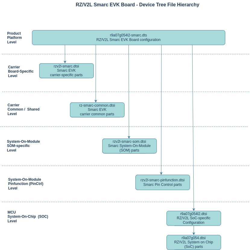
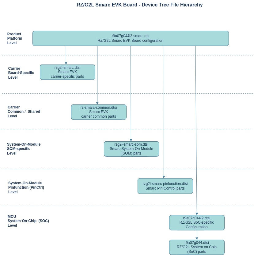
After the build has completed, the device tree source file is located at tmp/work-shared/smarc-rzv2l/kernel-source/arch/arm64/boot/dts/renesas/r9a07g054l2-smarc.dts inside the build/ directory.
it includes multiple "device tree include" files (*.dtsi):
#include "r9a07g054l2.dtsi"
#include "rzg2l-smarc-som.dtsi"
#include "rzg2l-smarc-pinfunction.dtsi"
#include "rz-smarc-common.dtsi"
#include "rzg2l-smarc.dtsi"
To update the pin assignments, rzg2l-smarc-pinfunction.dtsi needs to be patched.
- Create a temporary work directory with:
$ mkdir ~/tmp - Copy the device tree file that is going to be patched and copy it to
~/tmp:
$ cp ./build/tmp/work-shared/smarc-rzv2l/kernel-source/arch/arm64/boot/dts/renesas/rzg2l-smarc-pinfunction.dtsi ~/tmp/ - Change to the directory
$ cd ~/tmp - Create a copy of the just copied device tree include file:
$ cp rzg2l-smarc-pinfunction.dtsi rzg2l-smarc-pinfunction.dtsi.orig - Modify the originally copied file in your favourite editor:
$ vim rzg2l-smarc-pinfunction.dtsi - Create patch with
$ git diff --no-index rzg2l-smarc-pinfunction.dtsi.orig rzg2l-smarc-pinfunction.dtsi > 0001-mistysom-pin-updates.patch - view the patch file
$ vim 000-mistysom-pin-updates.patchto confirm the changes - update the
aandbfilenames on the top of the file (to indicate the correct paths) - Change the paths from:
--- a/rzg2l-smarc-pinfunction.dtsi.orig
+++ b/rzg2l-smarc-pinfunction.dtsi
to:
--- a/arch/arm64/boot/dts/renesas/rzg2l-smarc-pinfunction.dtsi
+++ b/arch/arm64/boot/dts/renesas/rzg2l-smarc-pinfunction.dtsi
- Add a custom Yocto Layer that applies the patch to the build
- Copy the patch to the custom layer (called meta-mistysom in this example)
- Return back into the build directory
$ cd ~/rzv_vlp_v3.0.0/ - Source the environment (just in case
$ source poky/oe-init-build-env) - Leave the build/ directory
$ cd .. - Create a recipe dir
$ mkdir -p meta-mistysom - Change into the newly created directory
$ cd meta-mistysom - Create a kernel-patch dir
$ mkdir -p recipes-kernel/linux/ - Copy the patch file into the newly created dir
$ cp ~/tmp/0001-example.patch recipes-kernel/linux/ - Lookup kernel name
$ oe-pkgdata-util lookup-recipe kernel
expected resultlinux-renesas - Create append file with kernel name (for any kernel version)
$ vim recipes-kernel/linux/linux-renesas_%.bbappend
- Return back into the build directory
Access device tree information from User Space
Revision History
| Version | Description of Changes | Date |
| 1.0 | Initial Version | 10/21/2022 |
Introduction
The value of some dtb entry might have to be checked for debugging, or to verify that the dtb really got updated after it was modified, etc. Although a .dts-file-like view of the device tree which was loaded cannot be achieved, values can be verified using the entries on the in /proc/device-tree.
Something similar to the following can be seen on the command prompt in Linux in the /proc/device-tree directory:
root@j7-evm:~# ls /proc/device-tree/
#address-cells  firmware                l3-cache0
#size-cells     fixedregulator-evm12v0  main_r5fss_cpsw9g_virt_mac0
__symbols__     fixedregulator-sd       memory@80000000
aliases         fixedregulator-vsys3v3  model
chosen          fixedregulator-vsys5v0  name
compatible      gpio-keys               pmu
connector       interconnect@100000     reserved-memory
cpus            interrupt-parent        serial-number
dma_buf_phys    ion                     sound@0
dummy-panel     l2-cache0               timer-cl0-cpu0
Typical usage examples
-
If the exact path of the device tree entry to check is not known. There is a symbol directory in
/proc/device-tree, which is very helpful in such cases. It has an entry for each symbol label in the device tree. The exact path for a symbol can be found by running thecatcommand on an entry. Following is an example demonstrating the use:root@j7-evm:~# cat /proc/device-tree/__symbols__/main_i2c0 /interconnect@100000/i2c@2000000 root@j7-evm:~# ls /proc/device-tree/interconnect@100000/i2c@2000000/ #address-cells clock-names gpio@20 name pinctrl-names #size-cells clocks gpio@22 phandle power-domains clock-frequency compatible interrupts pinctrl-0 reg -
The value of a device tree entry can be checked using the
catcommand if it is a string. If the value is an integer or some numeric data, however, thexxdcommand will have to be used instead ofcat, to get output in a readable format. Following is an example demonstrating the use:# Example for a string value root@j7-evm:~# cat /proc/device-tree/interconnect@100000/i2c@2000000/compatible ti,j721e-i2cti,omap4-i2c # Example for an integer value root@j7-evm:~# xxd -g4 /proc/device-tree/interconnect@100000/i2c@2000000/clock-frequency 00000000: 00061a80 .... # The above value is in hexadecimal. You can calculate its value in decimal by using the following command root@j7-evm:~# echo $((0x00061a80)) 400000 -
One common scenario of a device tree change is tweaking the memory for remoteproc processors like R5F. You can check if it got updated correctly, by running a command similar to the following for the specific processor core.
# Finding symbols for R5Fs
root@j7-evm:~# ls /proc/device-tree/__symbols__/main_r5fss*
/proc/device-tree/__symbols__/main_r5fss0                          /proc/device-tree/__symbols__/main_r5fss0_core1_dma_memory_region  /proc/device-tree/__symbols__/main_r5fss1_core0_memory_region
/proc/device-tree/__symbols__/main_r5fss0_core0                    /proc/device-tree/__symbols__/main_r5fss0_core1_memory_region      /proc/device-tree/__symbols__/main_r5fss1_core1
/proc/device-tree/__symbols__/main_r5fss0_core0_dma_memory_region  /proc/device-tree/__symbols__/main_r5fss1                          /proc/device-tree/__symbols__/main_r5fss1_core1_dma_memory_region
/proc/device-tree/__symbols__/main_r5fss0_core0_memory_region      /proc/device-tree/__symbols__/main_r5fss1_core0                    /proc/device-tree/__symbols__/main_r5fss1_core1_memory_region
/proc/device-tree/__symbols__/main_r5fss0_core1                    /proc/device-tree/__symbols__/main_r5fss1_core0_dma_memory_region

# Finding the location from the symbols
root@j7-evm:~# cat /proc/device-tree/__symbols__/main_r5fss0_core0_memory_region
/reserved-memory/r5f-memory@a2100000

root@j7-evm:~# cat /proc/device-tree/__symbols__/main_r5fss0_core0_dma_memory_region
/reserved-memory/r5f-dma-memory@a2000000

# Checking the values
root@j7-evm:~# xxd -g4 /proc/device-tree/reserved-memory/r5f-memory@a2100000/reg
00000000: 00000000 a2100000 00000000 01f00000  ................

root@j7-evm:~# xxd -g4 /proc/device-tree/reserved-memory/r5f-dma-memory@a2000000/reg
00000000: 00000000 a2000000 00000000 00100000  ................
Device Tree Hierarchy for MistySOMG2L and MisdtySOMV2L
The below diagrams give an overview of how the device trees are separated:
V2L
G2L
How to Add Device a Custom Device
Revision History
| Version | Description of Changes | Date |
| 1.0 | Initial Version | 02/08/20233 |
Introduction
The Prerequisite for the below steps is that the new device already is supported by the Linux kernel version we are about to modify. To confirm driver support for a specific kernel version, search the kernelconfig website.
To add a custom device to the MistySOM distribution, multiple steps are required. They can be separated as follows:
- Update Linux kernel configuration to compile the driver for the new device
- Patch the device tree to configure the driver for the new device.
- Rebuild the kernel & device tree
- Load & boot the rebuilt files for testing
1. Update Linux kernel configuration to compile the driver for the new device
The prerequisite for this step is, that the build container from the repository has been cloned and started with the dev shell argument. To find out more about it, please see Description of advanced container options in the Getting Started Guide and start the container with the -n argument.
When the container is started, the directory is changed and the build-environment is sourced, the present directory should be build/. From here,
bitbake linux-renesas -c menuconfig
can be invoked to launch menuconfig(a ncruses based configuration utility) to customize the Linux kernel options. Configuration options can be difficult to find and you can use kernelconfig.io to find if support for your device is part of the Linux kernel at a selected version. It will also give directions, about where the configuration option can be found and enabled.
After the option has been enabled, save the configuration (default filename .config is fine)and exit the menuconfig utility.
Back on the shell,
bitbake linux-renesas -c diffconfig
can be invoked to create a fragment of the configuration differences. Copy the fragment from $WORK/build/tmp/work/smarc-rz_rzv2l-poky-linux/linux-renesas/[kernelversion...]/ to $WORK/meta-renesas/recipes-common/recipes-kernel/linux/linux-renesas/ and rename it for ease of management (e.g. MY_DEVICE.cfg).
if you look at the contents of your MY_DEVICE.cfg it should look similar to:
cat $WORK/meta-renesas/recipes-common/recipes-kernel/linux/linux-renesas/MY_DEVICE.cfg
CONFIG_TYP_MY_DEVICE=y
After the fragment has been added to, edit the kernel bitbake recipe located at $WORK/meta-renesas/recipes-common/recipes-kernel/linux/linux-renesas_#.##.bb and add MY_DEVICE.cfg to the configuration fragments listed under SRC_URI_append = " \ like so:
SRC_URI_append = " \
file://MY_DEVICE.cfg \ (new)
"
invocation of
bitbake mistysom-image
will now build the kernel with the newly added device driver included.
2. Patch the device tree to configure the driver for the new device.
An excellent tutorial that relates to editing the device tree, can be found here: Intro to Embedded Linux Part 5 - How to Enable I2C in the Yocto Project.
Also see this article: Customize Device tree
3. Rebuild the kernel & device tree
Invoke
bitbake virtual/kernel -c compile -f && bitbake virtual/kernel
to re-compile the kernel and the device tree
4. Load & boot the rebuilt files for testing
Prepare a uSD card according to instructions here, copy the Linux kernel and the device tree blob (.dtb) files to the first partition (see here for details about the output files) and extract the root filesystem to the second partition.
Audio Codec
Device Tree implementation for the Audio CODEC TLV320AIC23B
Revision History
| Version | Description of Changes | Date |
| 1.0 | Initial Version | 10/21/2022 |
Introduction
The Audio CODEC is connected on the MistyCarrier as follows:
sound {
        compatible = "fsl,imx-audio-tlv320";
        model = "imx-tlv320";
        ssi-controller = <&ssi0>;
        audio-codec = <&codec>;
        audio-routing =
            "MICIN", "Mic Jack",
            "Headphone Jack", "LHPOUT",
            "Headphone Jack", "RHPOUT";
        mux-int-port = <2>;
        mux-ext-port = <5>;
    };
   sound-hdmi {
       compatible = "fsl,imx6q-audio-hdmi",
                "fsl,imx-audio-hdmi";
&audmux {
    status = "okay";
    pinctrl-names = "default";
    pinctrl-0 = <&pinctrl_audmux_sk>;
+};
&i2c3 {
    pinctrl-0 = <&2c3_ins>;
    pinctrl-names = "default";
    clock-frequency = <100000>;

    status = "okay";

    codec: tlv320aic23@1a {
        compatible = "ti,tlv320aic23";
        clocks = <&clks 200>;
        clock-frequency = <12000000>;
        reg = <0x1a>;
    };
about clock
        clocks = <&clks 200>;
        clock-frequency = <12000000>;

&iomuxc {
    pinctrl-names = "default";
    pinctrl-0 = <&pinctrl_hog>;
    hog {
        pinctrl_hog: hoggrp {
            fsl,pins = <
                /* SD1_DET */
                MX6QDL_PAD_SD4_DAT1__GPIO2_IO09             0x80000000
                /* AUDIO_MCLK */
                MX6QDL_PAD_NANDF_CS2__CCM_CLKO2             0x80000000
    audmux {
        pinctrl_audmux_sk: audmux-sk {
            fsl,pins = <
                MX6QDL_PAD_KEY_COL0__AUD5_TXC               0x130b0
                MX6QDL_PAD_KEY_ROW0__AUD5_TXD               0x130b0
                MX6QDL_PAD_KEY_COL1__AUD5_TXFS              0x130b0
                MX6QDL_PAD_KEY_ROW1__AUD5_RXD               0x130b0
            >;
        };
    };
&ssi0 {
    fsl,mode = "i2s-slave";
    status = "okay";
};
more information: https://community.nxp.com/t5/i-MX-Processors/How-to-enable-TLV320-on-IMX6Q/m-p/304913
Creating a custom Yocto Layer and Image
Introduction
This tutorial explains how a custom Yocto layer and a custom bitbake image can be created. It's only for display purposes and should not be used & deployed as is as setting the root password as shown below, is insecure.
- cd to Yoctro dir
- init env:
$ source poky/oe-init-build-env - leave build dir, do not change it, it's volatile:
$ cd .. - create custom layer:
$ bitbake-layers create-layer meta-custom - enter new layer directory:
$ cd meta-mistysom - create directory structure for custom image inside new recipe:
$ mkdir -p recipes-core/images(naming is important here) - Copy "core-image-minimal" recipe as template to customize:
$ cp ../poky/meta/recipes-core/images/core-image-minimal.bb recipes-core/images/custom-image.bb - Open
recipes-core/images/custom-image.bbfor customization:
$ vi recipes-core/images/custom-image.bb - Edit the file to look as depicted below:
SUMMARY = "My custom Linux image."

IMAGE_INSTALL = "packagegroup-core-boot ${CORE_IMAGE_EXTRA_INSTALL}"

IMAGE_LINGUAS = " "

LICENSE = "MIT"

inherit core-image
inherit extrausers

#Set rootfs  to 200MiB by default
IMAGE_OVERHEAD_FACTOR ?= "1.0"
IMAGE_ROOTFS_SIZE ?= "294800"

# Change root password (note the capital -P)
EXTRA_USERS_PARAMS = "usermod -P 'toor' root"
Changes are:
- Changed
SUMMARYchanged to descripe the custom image - Added
inherit extrausersto haave access to theusermodcommand - Added
IMAGE_OVERHEAD_FACTOR, for more details, see here - Changed
IMAGE_ROOTFS_SIZEto294800which equals a rootfs of about 200MiB (it's not exact) - Added
EXTRA_USERS_PARAMS = "usermod -P 'toor' rootto set the root password totoor(as an example - bad security practice, don't deploy!) (to edit the file hitito enter insert mode where the cursor is) - save the file and exit ([ESC] +
:x)
- Return to
builddirectory:
$ cd ../build/ - Modify
bblayers.confto add the layer to the build process:
$ vi conf/bblayers.confand add the path to new layer on the bottom of the list of existing layers:${TOPDIR}/../meta-custom \
- save the file and exit ([ESC] +
:x)
- There is a variable assignment that conflicts with the default password and as a result, the login does not work properly. In order to get around this, open
build/local.conf:
vi build/local.confand comment out theEXTRA_IMAGE_FEATURESline as follows:
( invisearch by entering/EXTRA_IMAGE_FEATURES, hitIto enter insert mode at beginning of line to insert the comment marker:#)#EXTRA_IMAGE_FEATURES ?= “debug-tweaks”
- save the file and exit ([ESC] +
:x)
- Invoke bitbake to build the custom-image:
$ bitbake custom-image(this will take a while to build & generate the output) - Upon completion, the custom images can be found in the output directory at
tmp/deploy/images/smarc-[boardname]
Bitbake CheatSheet
Revision History
| Version | Description of Changes | Date |
| 1.0 | Initial Version | 12/25/2022 |
Useful Bitbake commands
- Compile single recipe with bitbake:
$ bitbake -b name_of_recipe
Additional Ressources
How to add a desired application to the MistySOM build and flow chart for bitbake recipe creation
How to create a custom bitbake recipe from a public repository
- Open a terminal and navigate to the directory where you want to store the recipe. We assume that the application to add is called DesiredApp(adjust the name accordingly).
- Create a new file with the .bb extension using your preferred text editor. For this example, we'll call the file "desiredapp.bb".
- Start the recipe by defining the metadata. Here's an example:
SUMMARY = "Recipe for DesiredApp"
DESCRIPTION = "Compiles DesiredApp from a public GitHub repository"
LICENSE = "MIT"
LIC_FILES_CHKSUM = "file://LICENSE;md5=4d92cd373abda3937c2bc47fbc49d690"
SECTION = "examples"

SRC_URI = "git://github.com/user/DesiredApp.git;protocol=https"
SRCREV = "8fdea40ca783de02d3bc5833a97d6113e772495f"
S = "${WORKDIR}/git"

inherit cmake
- In the metadata, the SRC_URI parameter defines the URL of the GitHub repository to be cloned. The SRCREV parameter specifies which branch or commit to check out, it generally is recommended to use a SHA hash here to point to a particular commit in history. The S parameter specifies the location where the source code will be stored after cloning.
- The inherit parameter tells BitBake which class to inherit from for building the application. In this example, we're using the cmake class, which will automatically generate the Makefiles and build the application using the CMake build system, in other cases, you may need to use inherit makefile or inherit meson, depending on the application.
- Save and close the file.
- Add the recipe to your BitBake build environment by including it in your local.conf file. To do this, open local.conf and add the following line:
BBFILES += "/path/to/your/recipe/desiredapp.bb"
8. Save and close **local.conf**.
9. Build the recipe using the **bitbake** command:
bitbake desiredapp
This will download the source code from the GitHub repository, build the application using CMake, and create a package containing the compiled binaries. The package will be stored in the **tmp/deploy/** directory of your BitBake build environment.
How to create a custom bitbake recipe from local sources
Here is an example recipe that you can use:
SUMMARY = "Recipe for DesiredApp"
LICENSE = "CLOSED"

SRC_URI = "file://path/to/DesiredApp"

S = "${WORKDIR}"

do_compile() {
    ${CC} ${CFLAGS} ${LDFLAGS} ${WORKDIR}/DesiredApp.c -o ${WORKDIR}/DesiredApp
}

do_install() {
    install -d ${D}${bindir}
    install -m 0755 ${WORKDIR}/DesiredApp ${D}${bindir}
}

FILES_${PN} += "${bindir}/DesiredApp"
In the recipe, you will need to replace path/to/DesiredApp with the actual path to the source files for your DesiredApp.
Here's a brief explanation of what each section does:
- SUMMARY is a short description of the recipe.
- LICENSE specifies the license under which the recipe's files are distributed. In this case, I've used CLOSED as a placeholder for a closed-source license.
- SRC_URI specifies the location of the source files for your DesiredApp. In this example, I've assumed that the source files are available locally, so I've used file:// to specify the path to the files.
- S is a variable that points to the directory where the source files have been extracted.
- do_compile() is a function that contains the commands necessary to compile the application.
- do_install() is a function that contains the commands necessary to install the application on the target system.
- FILES_${PN} specifies which files should be included in the recipe's package. In this case, it includes the binary file DesiredApp in the bindir directory.
Once you have created the recipe, you can add it to your BitBake build by adding the recipe name to your build configuration file, like so:
IMAGE_INSTALL_append = " DesiredApp"
This will tell BitBake to include the DesiredApp recipe in the image it builds.
Read ADCs
In order to read raw values from the ADCs, use
# cat /sys/bus/iio/devices/iio\:device0/in_voltageN_raw
Where N is the channel number 0 - 5. In C the following can be used:
#include <stdio.h>

#define ADC_FILE "/sys/bus/iio/devices/iio:device0/in_voltage0_raw" // file path to ADC result

int main() {
FILE *fp;
int result;

fp = fopen(ADC_FILE, "r"); // open the file in read mode
if (fp == NULL) {
printf("Error opening file!\n");
return 1;
}

fscanf(fp, "%d", &result); // read the ADC result from the file
printf("ADC Result: %d\n", result); // print the ADC result

fclose(fp); // close the file

return 0;
}
GPIO Pins
GPIO Header
The 40-pin GPIO Header on MistyCarrier can be configured to expose different MistySOM functionalities including IIC, SPI or USART. The below table indicates the functionalities of each pin:
The column func0 indicates the default mux setting on the pin.
| func5 | func1 | func0 | desc | pin# | pin# | desc | func0 | func1 |
|---|---|---|---|---|---|---|---|---|
| 5V | 1 | 2 | 3.3V | |||||
| 1.8V | 3 | 4 | GND | |||||
| GND | 5 | 6 | 1.2V | |||||
| RIIC1_SDA | dedicated IIC | 7 | 8 | GND | ||||
| RIIC1_SCL | dedicated IIC | 9 | 10 | 2.5V | ||||
| RIIC2_SDA | P42_3 | 3.3V GPIO | 11 | 12 | GND | |||
| RIIC2_SCL | P42_4 | 3.3V GPIO | 13 | 14 | GND | |||
| NMI | input | 15 | 16 | Analog | ADC_CH0 | |||
| GND | 17 | 18 | Analog | ADC_CH1 | ||||
| shared with BLE | SCIF2_TXD | P48_0 | 3.3V GPIO | 19 | 20 | Analog | ADC_CH2 | |
| shared with BLE | SCIF2_RXD | P48_1 | 3.3V GPIO | 21 | 22 | Analog | ADC_CH3 | |
| shared with BLE | SCIF2_CTS | P48_3 | 3.3V GPIO | 23 | 24 | Analog | ADC_CH4 | |
| shared with BLE | SCIF2_RTS | P48_4 | 3.3V GPIO | 25 | 26 | Analog | ADC_CH5 | |
| GND | 27 | 28 | Analog | ADC_CH6 | ||||
| GND | 29 | 30 | Analog | ADC_CH7 | ||||
| GND | 31 | 32 | GND | |||||
| SCIF3_TXD | P0_0 | 3.3V GPIO | 33 | 34 | 3.3V GPIO | P43_0 | RSPI0_CK | |
| SCIF3_RXD | P0_1 | 3.3V GPIO | 35 | 36 | 3.3V GPIO | P43_1 | SPI0_MOSI | |
| SCIF3_SCK | P1_0 | 3.3V GPIO | 37 | 38 | 3.3V GPIO | P43_2 | SPI0_MISO | |
| GND | 39 | 40 | 3.3V GPIO | P43_3 | RSPI0_SSL |
GPIO Pads
Further GPIOs on MistyCarrier are available and accessible via through-hole pads between the RTC battery holder BT1 and the MistySOM connector J38 as shown in the picture below:
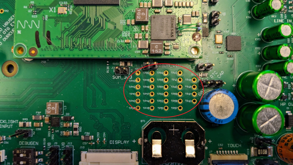
The column func0 indicates the default mux setting on the pin.
| pad# | desc | func0 | func1 | func2 | func3 |
|---|---|---|---|---|---|
| TP39 | DISP_DATA0 | P7_2 | DISP_DATA0 | ||
| TP40 | DISP_DATA1 | P8_0 | DISP_DATA1 | ||
| TP41 | DISP_DATA2 | P8_1 | DISP_DATA2 | ||
| TP42 | DISP_DATA3 | P8_2 | DISP_DATA3 | ||
| TP43 | DISP_DATA4 | P9_0 | DISP_DATA4 | ||
| TP44 | DISP_DATA5 | P9_1 | DISP_DATA5 | ||
| TP45 | DISP_DATA6 | P10_0 | DISP_DATA6 | ||
| TP46 | DISP_DATA7 | P10_1 | DISP_DATA7 | CAN0_TX | |
| TP47 | DISP_DATA8 | P11_0 | DISP_DATA8 | CAN0_RX | |
| TP48 | DISP_DATA9 | P11_1 | DISP_DATA9 | ||
| TP49 | DISP_DATA10 | P12_0 | DISP_DATA10 | ||
| TP50 | DISP_DATA11 | P12_1 | DISP_DATA11 | ||
| TP51 | DISP_DATA12 | P13_0 | DISP_DATA12 | ||
| TP52 | DISP_DATA13 | P13_1 | DISP_DATA13 | ||
| TP53 | DISP_DATA14 | P13_2 | DISP_DATA14 | IRQ 7 | |
| TP54 | DISP_DATA15 | P14_0 | DISP_DATA15 | ||
| TP55 | DISP_DATA16 | P14_1 | DISP_DATA16 | ||
| TP56 | DISP_DATA17 | P15_0 | DISP_DATA17 | ||
| TP57 | DISP_DATA18 | P15_1 | DISP_DATA18 | ||
| TP58 | DISP_DATA19 | P16_0 | DISP_DATA19 | IRQ 3 | |
| TP59 | DISP_DATA20 | P16_1 | DISP_DATA20 | IRQ 4 | |
| TP60 | DISP_DATA21 | P17_0 | DISP_DATA21 | IRQ 5 | |
| TP61 | DISP_DATA22 | P17_1 | DISP_DATA22 | IRQ 6 | |
| TP62 | DISP_DATA23 | P17_2 | DISP_DATA23 | ||
| TP63 | DISP_CLK | P6_0 | DISP_CLK | ||
| TP64 | DISP_DE | P7_1 | DISP_DE | ||
| TP65 | DISP_HSYNC | P6_1 | DISP_HSYNC | ||
| TP56 | DISP_VSYNC | P7_0 | DISP_VSYNC |
documentation about GPIO usage can be found here
Using GPIO on MistySOM and MistyCarrier to Test Toggling a LED With Libgpiod Utilities
Introduction
The ultimate purpose of this tutorial and test procedure is to demonstrate that selected digital General Purpose Input-Output (GPIO) pins on the MistySOM Carrier board have proper continuity and are fully functional for control of external digital i/o devices. Specifically, the procedure outlined here explains how the GPIO pins on the MistyCarrier board with a RZ/G2L MistySOM module can be used to toggle a LED on an attached breadboard by using the standard Linux libgpiod command line utilities which are provided in the Renesas VLP 3.0.x Linux RZ/G2L build with the custom MistySOM yocto Board Support Package. Individual pins on both the 40-pin J4 connector and debug pads for TP test pins can each be individually be connected and used to toggle the LED using the corresponding .sh shell script file which uses the libgpiod gpioset and gpiofind utilities.
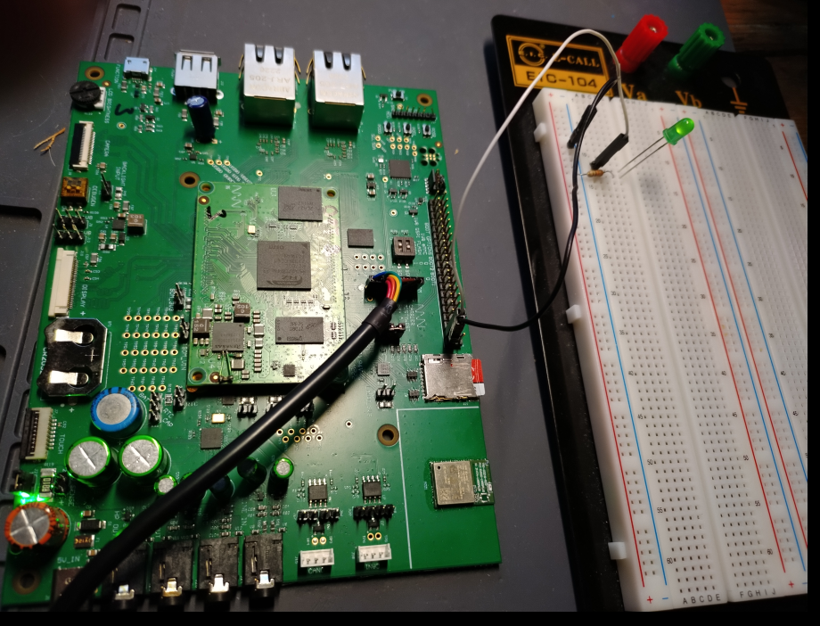 |
|---|
| Fig. 1 - MistySOM Carrier Board with Simple GPIO Test Setup Connection to LED Breadboard Circuit |
Materials:
MistyWest MistySOM EVK Kit (based on a MistySOM module using a Renesas RZ/G2L or RZ/V2L microcontroller as mezzanine module mounted on MistyCarrier). Make sure the MistySOM board boots from a micro SD Card running the latest MistySOM-specific RZ/G2L or RZ/V2L V3.0.x Linux image. A standard break-away 0.1" 2x20-pin dual male header should be soldered to the MistyCarrier J4 i/o pads if not populated.
Standard +3.3V FTDI TTL-232R-3V3-2MM USB to UART serial cable (https://ftdichip.com/products/ttl-232r-3v3/) connecting the 1x8-pin keyed J40 connector on the MistyCarrier to a USB 2.0 Type-A port on a host Linux or Windows PC.
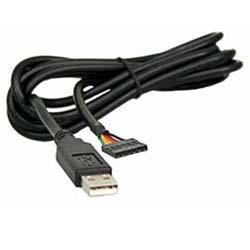
Terminal emulator software running on host PC for a serial terminal console session (e.g picocom, minicom on a Linux PC or puTTY, TeraTerm on a Windows PC).
Breadboard - Standard 0.1" solderless electronic prototyping breadboard with 400 or 800 tie-points with bus strip rows for power and ground rails.
Jumper Wires - standard F/F jumper wires with female connectors on both ends. Use these to jumper from any male header on the MistyCarrier board to any other pin on the prototyping breadboard. The LED toggle procedure verifies one GPIO pin at a time connected by a jumper to a single pin on header J4 (see Fig 3-4 below) or else a pin on from one of test points TP39-TP66 on the debug pads of the MistyCarrier (see Fig 6-9 below).
Jumper Pins - assorted 0.1" breakaway rectangular jumper pins for connecting jumpers to breadboard
Resistor - A standard 330Ω carbon-film resistor colour code Orange-Orange-Brown-Gold). Used as current-limiting or ballast resistor attached to anode of LED diode. A 330Ω value is conservative and should provide a reasonable LED intensity without crossing the forward-based junction voltage threshold allowing excessive current flow.
LED - One standard 5mm through-hole Red or Green LED Diode rated for 1.8 to 3.1 Vf forward voltage (turn-on level) and 20mA current
Circuit
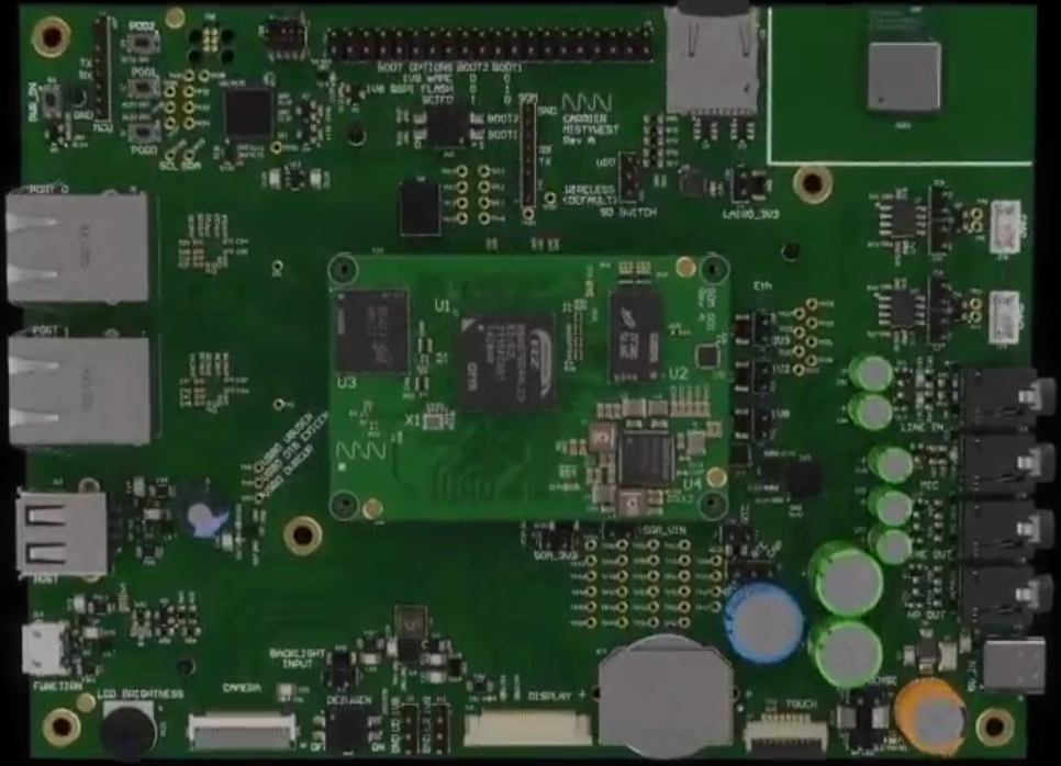
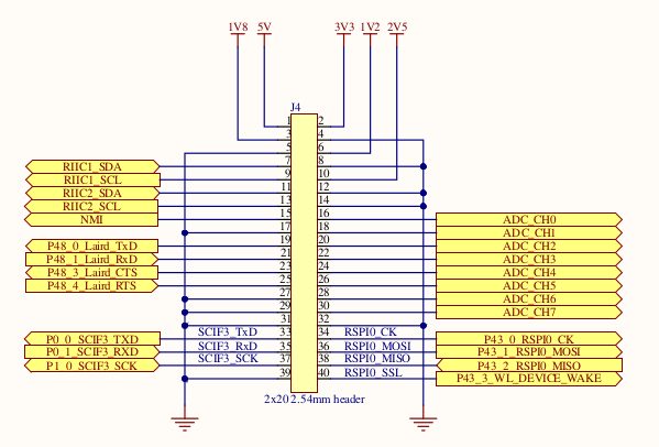
Refer to Fig 2 below showing the connector soldered to the J4 dual-row 2x20-pin header at the top centre of the image. The schematic for the MistySOM signals on this J4 connector is provided in Fig 3, and the mapping of the RZ/G2L Pin Mux functions to the pins is provided on Fig. 4 (or on GPIO pins). Finally Fig 5 shows an example of a Fritzing breadboard diagram of connecting the 3.3V J4 header pin 40 (3v3 RZ/G2L GPIO pin P43_3) via the 330Ω resistor to the LED anode. The LED cathode is connected indirectly to pin 4 GND on the J4 header via the GND rail on the breadboard. Toggling the LED on and off is covered in the test procedure section further below. For testing GPIO pin P43_3 on J4 pin 40, the corresponding gpio_J4_pin_40_toggle script is used to toggle the LED on and off 3 times at 1-second intervals. For testing other GPIO signals on the J4 header, the jumper should be reconnected to the desired GPIO header pin, and the corresponding gpio_J4_pin_NN_toggle.sh should be invoked from the command line.
 |
|---|
| Fig 2 - MistyCarrier with mezzanine MistySOM showing J4 2x20-pin header at top center |
 |
|---|
| Fig. 3 - MistyCarrier J4 Connector schematic pinout for pins 1-40 with available GPIO signal subset |
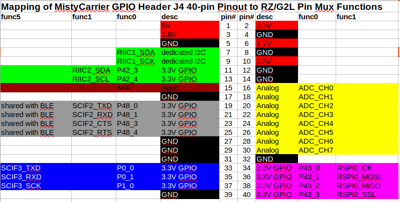 |
|---|
| Fig. 4 - Mapping of MistyCarrier J4 Header pinout to Available GPIO RZ/G2L pins on func0 pin mux selection |
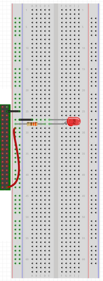 |
|---|
| Fig. 5 - Breadboard Circuit Image of J4 pin 40 (3v3 RZ/G2L GPIO pin P43_3) connected via resistor to LED anode. |
The schematic for the MistySOM GPIO signals on the Test Points TP39-TP66 debug pads in provided in Fig 6 below, and the mapping of the RZ/G2L Pin Mux functions to the TPnn test point pins is provided in Fig. 7 (or on GPIO pins). Pictures of the Debug Pad Test Points on the MistyCarrier are shown in Fig 8 and Fig. 9. For testing the LED toggling of the debug test points, each TPnn pin is iteratatively or successively connected via the 330Ω resistor to the LED anode. As previously, the LED cathode is connected indirectly to pin 4 GND on the J4 header via the GND rail on the breadboard. Toggling the LED on and off is covered in the test procedure section further below. For example, to test test point TP39 (GPIO P7_2), the gpio_debug-pad_TP39_toggle.sh script is used to toggle the LED on and off 3 times at 1-second intervals. For testing other GPIO signals on the TP39-TP66 debug Test Points, the jumper should be reconnected to the desired TPnn header pin, and the corresponding gpio_debug-pad_TP39_toggle.sh script should be invoked from the command line.
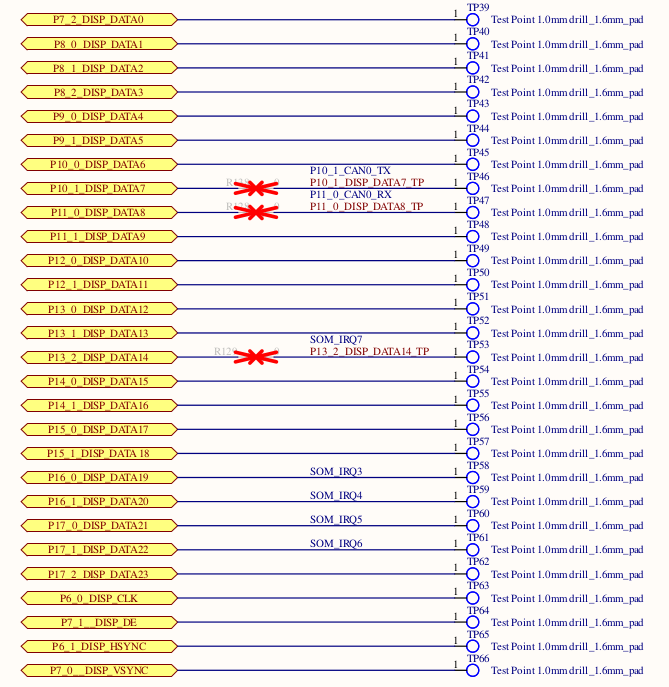 |
|---|
| Fig. 6 - MistyCarrier Debug Pads TP39 to TP66 - Schematic excerpt |
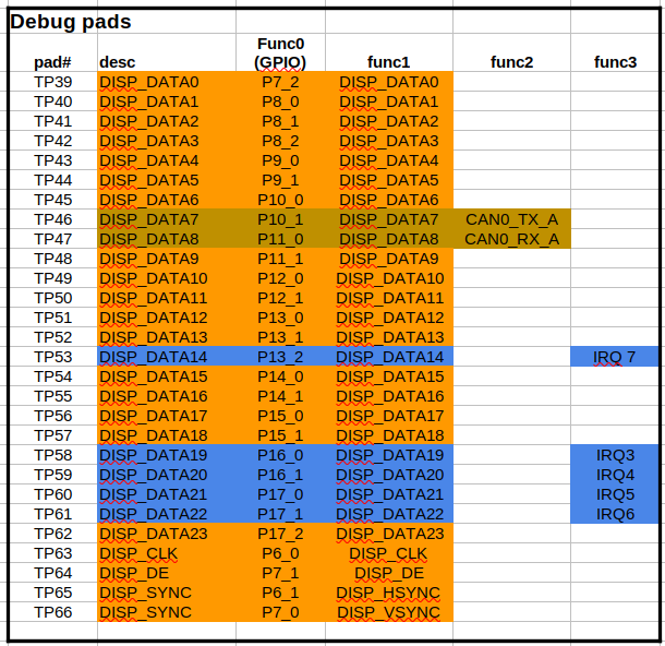 |
|---|
| Fig. 7 - MistyCarrier Debug Pads TP39 to TP66 - GPIO PinMux Mapping for mux option func0 (GPIO) |
 |
|---|
| Fig. 8 - Position of Test Point TP39-TP66 Debug Pads on MistyCarrier |
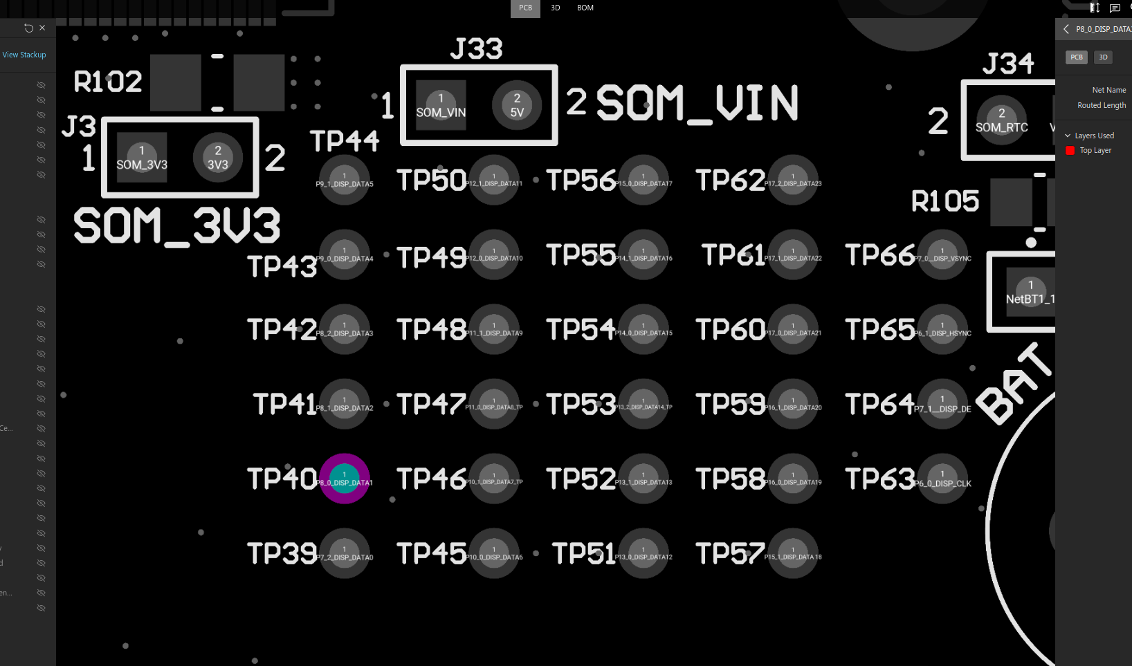 |
|---|
| Fig. 9 - Close-up Image of Test Point TP39-TP66 Debug Pads on MistyCarrier |
Test Procedure Using libgpiod tools
The libgpiod GPIO device library package for Linux is a user-mode C library and also a set of command tools for interacting with the Linux GPIO character device. This library encapsulates the ioctl() calls and data structures using a straightforward API. The respective Renesas RZ/G2L or RZ/V2L images encapsulating the MistySOM-specific kernel image and BPS board support library already contain the libgpiod package in the build image, and the appropriate Device Tree definitions for pinctrl pin muxing. For more information see: https://git.kernel.org/pub/scm/libs/libgpiod/libgpiod.git/about/.
Libgpiod Command Line Tools:
For the purposes of toggling a LED using GPIO, we only will need to use the libgpiod CLI tools from the Bash shell. In the past, GPIO was accessed by the Shell from the sysfs interface. As of Linux version 4.8, this use has been deprecated. The six command line tools in libgpiodare a better way to access the libgpiod driver API via the shell.
- gpiodetect: list all gpiochips present on the system, their names, labels, and number of GPIO lines
- gpioinfo: list all lines of specified gpiochips, their names, consumers, direction, active state, and additional flags
- gpioget: read values of specified GPIO lines
- gpioset: set values of specified GPIO lines, potentially keep the lines exported and wait until timeout, user input or signal
- gpiofind: find the gpiochip name and line offset given the line name
- gpiomon: wait for events on GPIO lines, specify which events to watch, how many events to process before exiting or if the events should be reported to the console
libgpiod Examples
-
gpiodetect: To find out which GPIO banks and how many GPIO lines are available on the hardware. For MistySOM RZ/G2L version and MistyCarrier:
root@smarc_rzg2l:/# gpiodetect
gpiochip0 [11030000.pin-controller] (392 lines)
gpiochip1 [sx1502q] (8 lines)
gpiochip2 [sx1502q] (8 lines)
The gpiochip0 bank is used for the internal on-chip RZ/G2L SoC peripheral which has 392 lines. The gpiochip1 and gpiochip2 banks are used respectively with two Semtech SX1502q i2c GPIO port expanders to read 8 GPIO pins in each bank for the MistySOM PCB board revision bit values (gpiochip1) and MistyCarrier PCB board revision bit values (gpiochip2). Discussion of configuring and reading these PCB revision resistor bit values is outside the scope of this GPIO LED toggle application note.
-
gpioinfo: List all lines of specified gpiochips, their names, direction, active state and additional flags
root@smarc-rzg2l:/# gpioinfo gpiochip0
    gpiochip0 - 392 lines:

    line   0:       "P0_0" "gpio_hdr_pin33" output active-high [used]
    line   1:       "P0_1" "gpio_hdr_pin35" output active-high [used]
    line   2:       "P0_2"       unused   input  active-high
    line   3:       "P0_3"       unused   input  active-high
    line   4:       "P0_4"       unused   input  active-high
    line   5:       "P0_5"       unused   input  active-high
    line   6:       "P0_6"       unused   input  active-high
    line   7:       "P0_7"       unused   input  active-high
    line   8:       "P1_0" "gpio_hdr_pin37" output active-high [used]
    line   9:       "P1_1"       unused   input  active-high
    line  10:       "P1_2"       unused   input  active-high
    line  11:       "P1_3"       unused   input  active-high
.
.
    line 383:      "P47_7"       unused   input  active-high
    line 384:      "P48_0" "gpio_hdr_pin11" output active-high [used]
    line 385:      "P48_1" "gpio_hdr_pin21" output active-high [used]
    line 386:      "P48_2"       unused   input  active-high
    line 387:      "P48_3" "gpio_hdr_pin23" output active-high [used]
    line 388:      "P48_4" "gpio_hdr_pin25" output active-high [used]
    line 389:      "P48_5"       unused   input  active-high
    line 390:      "P48_6"       unused   input  active-high
    line 391:      "P48_7"       unused   input  active-high
-
gpiofind: Find the gpiochip name and line offset given the line name.
root@smarc-rzg2l:/# gpiofind "P48_0"
gpiochip0 384
-
gpioset: Set the values of specified GPIO lines. gpioset expects the bank, gpiochip, GPIO line and the value to be set, 1 for HIGH and 0 for LOW active-high standard
⚠ Note: gpioset (and all libgpiod apps) will revert the state of a GPIO line back to its original value when it exits. For this reason if you want the state to persist you need to instruct gpioset to wait for a signal and optionally detach and run in the background.
Display help for the gpioset command:
# gpioset --help
Usage: gpioset [OPTIONS]  = = ...
Set GPIO line values of a GPIO chip
Options:
  -h, --help:           display this message and exit
  -v, --version:        display the version and exit
  -l, --active-low:     set the line active state to low
  -m, --mode=[exit|wait|time|signal] (defaults to 'exit'):
                tell the program what to do after setting values
  -s, --sec=SEC:        specify the number of seconds to wait (only valid for --mode=time)
  -u, --usec=USEC:      specify the number of microseconds to wait (only valid for --mode=time)
  -b, --background:     after setting values: detach from the controlling terminal

Modes:
  exit:         set values and exit immediately
  wait:         set values and wait for user to press ENTER
  time:         set values and sleep for a specified amount of time
  signal:       set values and wait for SIGINT or SIGTERM
Examples:
root@smarc-rzg2l:/# gpioset gpiochip0 384=1   ### Set line 384 of gpiochip0 to 1 (but it will also immediately go back to 0)
root@smarc-rzg2l:/# gpioset --mode=signal --background gpiochip0 384=1   ### Set pin to 1, but continue to run in the background so the pin will stay high or 1
root@smarc-rzg2l:/# gpioset --mode=time --sec=1 gpiochip0 384=0  ### toggle the pin for 1 sec
root@smarc-rzg2l:/# gpioset --mode=wait gpiochip0 384=0 ### toggle pin & wait for press ENTER
-
gpioset and gpiofind combination: Set values of GPIO by using gpiofind to lookup the signal name to find the pin offset in the bank.
E.G. To toggle MistyCarrier J4 pin 19 (GPIO P48_0), instead of using
gpioset --mode=time --sec=1 384=1
we can instead use the command
gpioset --mode=time --sec=1 `gpiofind "P48_0"`=1
In this example, gpiofind is used to lookup GPIO pin P48_0 to return the offset 384 which is passed as the bank pin offset parameter to the gpioset command. All of the gpio_J4_pin_nn_toggle.sh and gpio_debug-pad_TPnn_toggle.sh scripts toggle LEDs using this parameter lookup trick to determine the correct pin offset to pass to the gpioset commands.
Using GPIO LED Toggle Scripts:
To make use of the GPIO LED toggle scripts, perform the following steps:
-
Determine which GPIO pin you wish to test from either the 40-pin J4 header or else the TPnn Debug test points (refer to the GPIO pins page).
-
Connect the jumper attached to the 3V3 end of the series current limiting resistor connected to the LED anode to the desired pin (either on J4 header or on desired TP test point).
-
Invoke the corresponding test script toggling the LED using the corresponding GPIO pin.
For the J4 40-pin header, use one of the gpio_J4_pin_nn_toggle.sh scripts. For example, we can toggle the LED using J4 pin 40 using the script command:
root@smarc-rzg2l:/# ./gpio_J4_pin_40_toggle.shFor the TP39 to TP66 test points, use one of the pio_debug-pad_TPnn_toggle.sh scripts. For example, we can toggle the LED using pin TP39 using the script command:
root@smarc-rzg2l:/# ./gpio_debug-pad_TP39_toggle.shToggle swcripts are in the MistySOM/aux repository.
How to set the pin mux
- Find out Mux position for the respective pin from the datasheet at: RZ Family / RZ/G, RZ/V Series and find the corresponding mux position for the desired functionality with the RZG2L_pinfunction_List spreadsheet.
- Then preparepinmux function call according to
RZG2L_PORT_PINMUX(A, B, C)where: -
A= portnumber (e.g. forP40_1it would be40)B= pin number (e.g. forP40_0it would be0)C= mux position according to the above linked pinfunction spreadsheet
- Prepare a
.dtsfile to override any previous/existing pin mux setting. Prepare a file with the following example contents:
   &pinctrl {
	can0_pins: can0 {
		pinmux = <RZG2L_PORT_PINMUX(10, 1, 2)>, /* TX */
			 <RZG2L_PORT_PINMUX(11, 0, 2)>; /* RX */
	};

	can1_pins: can1 {
		pinmux = <RZG2L_PORT_PINMUX(40, 0, 3)>, /* TX */
			 <RZG2L_PORT_PINMUX(40, 1, 3)>; /* RX */
	};
 };
and store the file in meta-mistysom/recipes-kernel/linux/dts/
6. Add a line like:
SRC_URI += "file://add-vsc8531-ethernet.dts"
to meta-mistysom/recipes-kernel/linux/linux-renesas_%.bbappend
7. Build and use the pins as configured
From: https://codebrowser.dev/linux/linux/include/dt-bindings/pinctrl/rzg2l-pinctrl.h.html
Setup WiFi
After you have connected a WiFi device, either using the Wireless/uSD pin on the MistyCarrier or plugging a supported WiFi adapter into the USB port, you can manually bring up the device with ifconfig wlan0 up. Confirm with ifconfig that your device is up:
# ifconfig
lo        Link encap:Local Loopback
          inet addr:127.0.0.1  Mask:255.0.0.0
          UP LOOPBACK RUNNING  MTU:65536  Metric:1
          RX packets:96 errors:0 dropped:0 overruns:0 frame:0
          TX packets:96 errors:0 dropped:0 overruns:0 carrier:0
          collisions:0 txqueuelen:1000
          RX bytes:6048 (5.9 KiB)  TX bytes:6048 (5.9 KiB)

wlan0     Link encap:Ethernet  HWaddr 18:A6:F7:0A:65:2D
          UP BROADCAST MULTICAST  MTU:1500  Metric:1
          RX packets:0 errors:0 dropped:0 overruns:0 frame:0
          TX packets:0 errors:0 dropped:0 overruns:0 carrier:0
          collisions:0 txqueuelen:1000
          RX bytes:0 (0.0 B)  TX bytes:0 (0.0 B)
Scan Access Points
In case you want to scan for every WiFi access point in your environment, you can use the command below to list their SSIDs:
iw wlan0 scan | egrep -w "signal:|SSID:" | paste -d ' ' - - | sort
If your WiFi module is working correctly, the output of the command above should be similar to this:
signal: -42.00 dBm      SSID: MistyWest
signal: -43.00 dBm      SSID: MistyDeploy
signal: -43.00 dBm      SSID: MistyGuest
signal: -60.00 dBm      SSID: TELUS1924
signal: -64.00 dBm      SSID: TELUSE55B
signal: -70.00 dBm      SSID: TELUSB840
signal: -71.00 dBm      SSID: SHAW-714340
Configuration
To connect to a specific WiFi access point, you need to provide the wpa_supplicant with the SSID and its passphrase using the command below:
mkdir /etc/wpa_supplicant
wpa_passphrase {YOUR-SSID} {YOUR-PASSPHRASE} > /etc/wpa_supplicant/wpa_supplicant-wlan0.conf
The newly created wpa_supplicant-wlan0.conf file will look like this:
network={
        ssid="{YOUR-SSID}"
        #psk="{YOUR-PASSPHRASE}"
        psk={64-hash-characters}
}
In case you are using WPA-Enterprise or other advanced configuration, see the wpa_supplicant.conf(5) examples and modify the file accordingly.
Connect
After the configuration file is ready, enable the two services below to connect to the SSID on each boot automatically:
systemctl enable --now wpa_supplicant@wlan0
Need Other Services to Run After WiFi is Connected?
Every service file with the parameter After=network-online.target will run after the WiFi is connected and an IP address is acquired.
Need a Static IP?
You will most likely be using a dynamic IP address and the DHCP client service obtains the IP per each connection. In case you want to use a static IP, create or edit the /etc/dhcpcd.conf file. For example:
interface wlan0
static ip_address=192.168.1.10/24
static routers=192.168.1.1
static domain_name_servers=192.168.1.1 8.8.8.8
More complicated configurations are possible, for example, combining with the arping option. See dhcpcd.conf(5) for details.
A restart will be required for the new configuration to work.
Check Connection
To check if you are on a working connection, you can check the output of iw wlan0 link command:
Connected to 62:22:32:28:53:7e (on wlan0)
        SSID: MW (Limited MAC)
        freq: 5200
        RX: 1028880 bytes (6289 packets)
        TX: 495655879 bytes (355731 packets)
        signal: -82 dBm
        rx bitrate: 6.0 MBit/s
        tx bitrate: 27.0 MBit/s

        bss flags:
        dtim period:    3
        beacon int:     100
To make sure your wlan0 device obtained a correct IP, you can check the output of ip a command:
1: lo: <LOOPBACK,UP,LOWER_UP> mtu 65536 qdisc noqueue qlen 1000
    link/loopback 00:00:00:00:00:00 brd 00:00:00:00:00:00
    inet 127.0.0.1/8 scope host lo
       valid_lft forever preferred_lft forever
2: can0: <NOARP40000> mtu 72 qdisc noop qlen 10
    link/[280]
3: can1: <NOARP40000> mtu 72 qdisc noop qlen 10
    link/[280]
4: eth0: <BROADCAST,MULTICAST> mtu 1500 qdisc noop qlen 1000
    link/ether 06:87:9a:a2:e3:4f brd ff:ff:ff:ff:ff:ff
5: eth1: <BROADCAST,MULTICAST> mtu 1500 qdisc noop qlen 1000
    link/ether a2:69:d7:df:09:5d brd ff:ff:ff:ff:ff:ff
6: wlan0: <BROADCAST,MULTICAST,UP,LOWER_UP> mtu 1500 qdisc noqueue qlen 1000
    link/ether 18:a6:f7:0a:65:2d brd ff:ff:ff:ff:ff:ff
    inet 192.168.1.10/24 brd 192.168.9.255 scope global dynamic wlan0     <------------- This line should exist
       valid_lft 560sec preferred_lft 271sec
Additionally, the ping mistywest.com command should show you that the domain name is resolved to a destination IP and you should receive responses once per second:
PING mistywest.com (172.67.213.204): 56 data bytes
64 bytes from 172.67.213.204: seq=0 ttl=59 time=27.031 ms
64 bytes from 172.67.213.204: seq=1 ttl=59 time=20.089 ms
64 bytes from 172.67.213.204: seq=2 ttl=59 time=17.214 ms
64 bytes from 172.67.213.204: seq=3 ttl=59 time=22.551 ms
Power Saving
By default, many WiFi modules, including the module on MistyCarrier, use an active power-saving configuration. To check the status of this configuration you can use the command below:
iw wlan0 get power_save
To disable the power saving temporarily, you can run the command below:
iw wlan0 set power_save off
If you want to make this setting permanent, you can create a service in /lib/systemd/system/wifi_powersave@.service with the content:
[Unit]
Description=Set WiFi power save %i
After=sys-subsystem-net-devices-wlan0.device

[Service]
Type=oneshot
RemainAfterExit=yes
ExecStart=/usr/sbin/iw dev wlan0 set power_save %i

[Install]
WantedBy=sys-subsystem-net-devices-wlan0.device
Then you can enable the service with systemctl enable wifi_powersave@off.service
Troubleshooting
-
The Wifi connection is unstable or slow compared to your other devices?
-
Check if you are using a different frequency with
iw wlan0 link. Different frequencies cover different ranges. For example, maybe other devices are using 2.4GHz frequency while your device is using 5GHz frequency which is faster but less stable in further distances. -
It might be because of the power saving. See the section below to turn it off and see if it improves your connection.
-
How To Set Up Socket CAN Interface
Introduction
The purpose of this tutorial is to demonstrate using the MistySOM Carrier board with a mezzanine MistySOM RZ/G2L module (shown in Fig. 1 below) to read and write data over CANbus to a Linux PC running a SocketCAN CANbus protocol analyzer such as SavvyCAN.
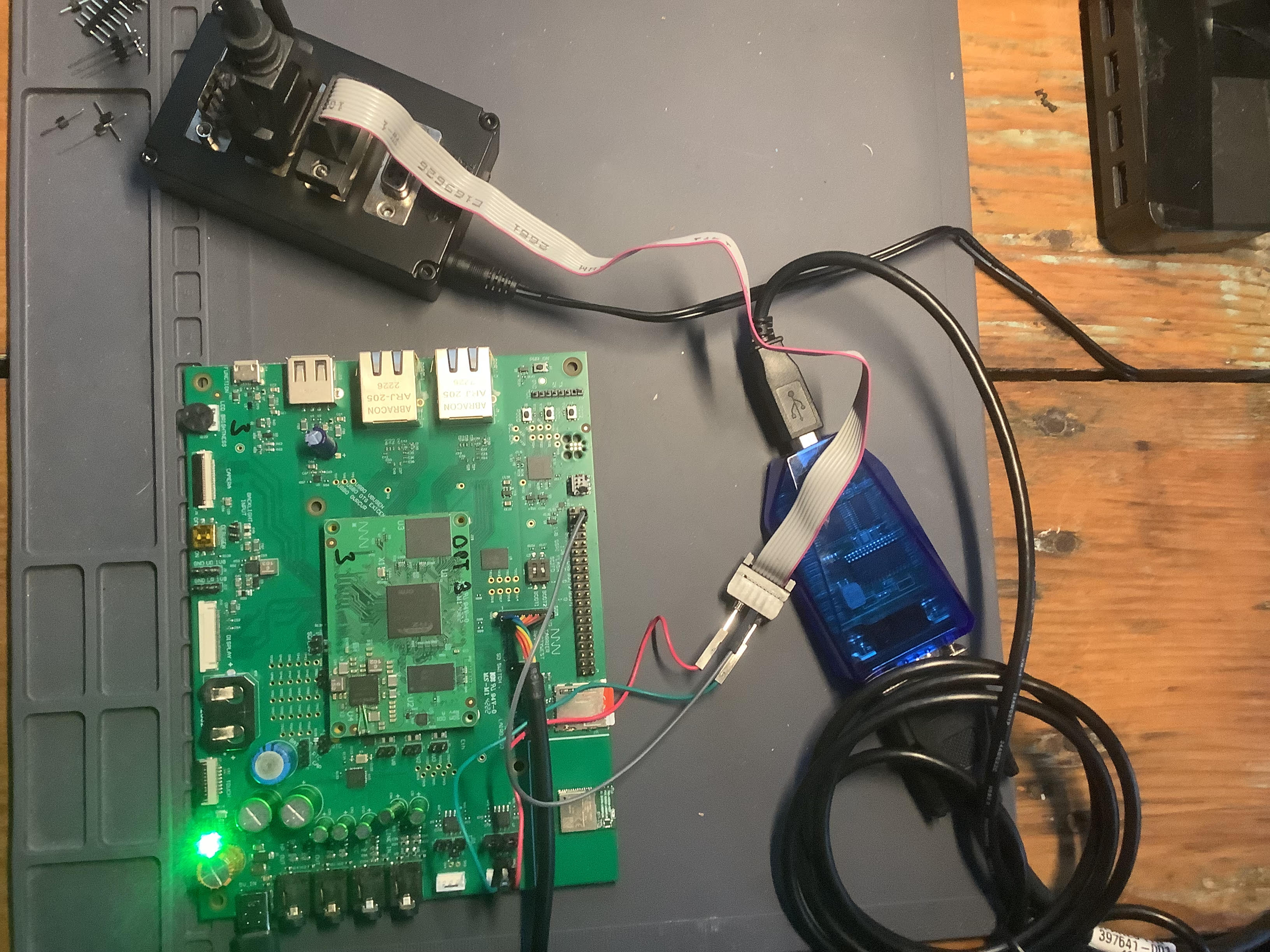 |
|---|
| Fig. 1 - Test Setup for reading and writing to CanBus from MistySOM RZ/G2L |
Materials:
- MistyWest MistySOM EVK Kit (based on a MistySOM module using a Renesas RZ/G2L or RZ/V2L microcontroller as a mezzanine module mounted on MistyCarrier). Make sure the MistySOM board boots from a micro SD Card running the latest MistySOM-specific RZ/G2L or RZ/V2L V3.0.x Linux image. A standard break-away 0.1" 2x20-pin dual male header should be soldered to the MistyCarrier J4 i/o pads if not populated. Refer to Fig 2 below.
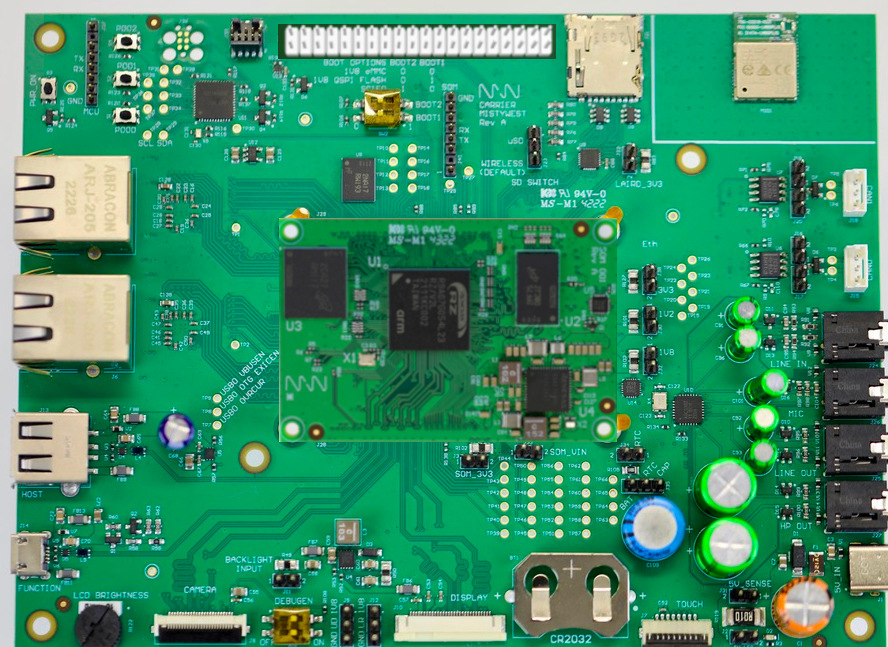 |
|---|
| Fig 2 - MistyWest EVK Kit with MistySOM mezzanine RZ/G2L module hosted on MistyCARRIER board. |
- Standard +3.3V FTDI TTL-232R-3V3-2MM USB to UART serial cable (https://ftdichip.com/products/ttl-232r-3v3/) connecting the 1x8-pin keyed J40 connector on the MistyCarrier to a USB 2.0 Type-A port on a host Linux or Windows PC. Refer to the image in Fig 3 below.
 |
|---|
| Fig 3 - FTDI TTL-232R-3V3 USB to UART serial cable |
-
Terminal emulator software running on host PC for a serial terminal console session (e.g picocom, minicom on a Linux PC or puTTY, TeraTerm on a Windows PC).
-
Molex Latch 3-pin Cable Socket to Wire Leads (p/n 2196791032) (one for each of CAN0 and CAN1 ports) Molex 3-wire PigTail connections for each of Ports CAN0 and CAN1 on MistyCarrier board. Refer to Fig 4 below showing Molex pigtail as connected to PEAK PCAN-Adapter D-Sub connector screw terminals.
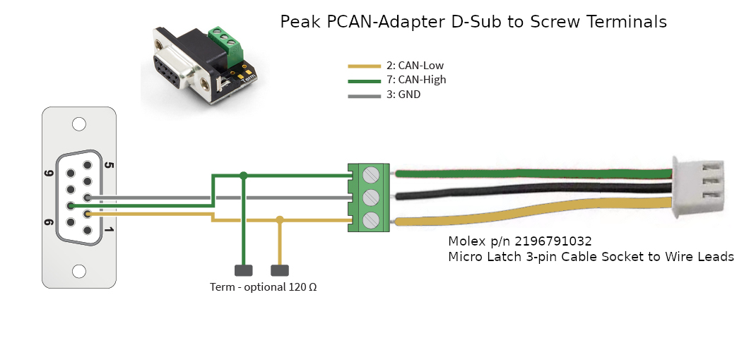 |
|---|
| Fig. 4 - Close-up of Molex Pigtail connector attached to PEAK PCAN-Adapter DB-9 D-Sub adapter |
-
**Peak PCAN-Adapter D-Sub to Screw Terminals Pigtail connector (p/n IPEK-003025) (one for each set of Molex Latch 3-pin pigtail wire leads for CAN0 and CAN1 ports) ** - Refer to Fig 4 above showing Molex pigtail as connected to PEAK PCAN-Adapter D-Sub connector screw terminals. Optional 120-ohm termination jumpers are not installed since CAN termination is installed on the MistyCARRIER board.
-
Kvaser T-CANnector V2 (p/n 73-30130-00776-5) - The T-CANnector V2 serves as a DB-9 CANbus hub with 3 female and 1 male DB-9 connectors. Refer to Fig 5 below. Each of the PEAK PCAN-Adapter terminals for the CAN0 and CAN1 ports from the MistyCarrier can connect to the T-CANnector hub. All peer devices connected to the CAN segment on the Kvaser T-CANnector V2 hub can communicate with each other.
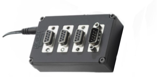 |
|---|
| Fig 5 - Kvaser T-CANnector V2 (p/n 73-30130-00776-5) |
- Lawicel CANUSB CAN to USB Interface Converter
The Lawicel CANUSB interface (refer to Fig 6 below) is a relatively inexpensive CAN-to-USB dongle that plugs into any PC USB Port and gives SocketCAN connectivity to a host Linux PC. This means it can be treated by software as a standard COM Port (virtual serial RS232 port) with the FTDI USB drivers which eliminates the need for any extra drivers (DLL) or optionally by installing a direct driver DLL (D2XX) together with the CANUSB DLL for faster communications and higher CAN bus loads. The Lawicel CANUSB converter should be connected to the P4 DSUB-9 plug port on the Kvaser T-CANnector V2 (rather than the P1, P2 or P3 DSUB-9 socket connectors). Also, the switch for the 120 ohm termination resistor on the Kvaser T-CANnector V2 hub should be enabled to establish termination for the Lawicel adapter at it's end of the CANbus segment.
|  |
|---|
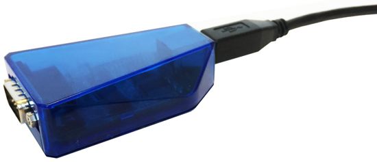 |
| Fig. 6 - Lawicel CANUSB CAN to USB Adaptor Dongle |
-
SavvyCAN CAN analyzer software for Linux - SavvyCAN (https://www.savvycan.com/) is a cross-platform QT-based CAN bus capture and analysis software tool (supported on Linux) which is able to use any socketCAN compatible device. SavvyCAN can use any CAN interface supported by QT's SerialBus system (PeakCAN, Vector, SocketCAN, Lawicel CANUSB, J2534, etc). It can capture and send to multiple buses and CAN capture devices at once. SavvyCAN has many functions specifically meant for reverse engineering data found on the CAN bus:
- Ability to capture even very highly loaded buses
- Ability to connect to many dongles simultaneously
- Scan captured traffic for data that looks coherent
- Show ASCII of captured data to find things like VIN numbers and traffic to and from the radio
- Graph data found on the bus
- Load and Save many different file formats common to CAN capture tools (Vector captures, Microchip, CANDo, PCAN, and many more)
- Load and Save DBC files. DBC files are used to store definitions for how data are formatted on the bus. You can turn the raw data into things like RPM, odometer readings, and more.
- UDS scanning and decoding
- Scripting interface to be able to expand the scope of the software
MistyCarrier RZ/G2L interface for reading and writing to CANbus
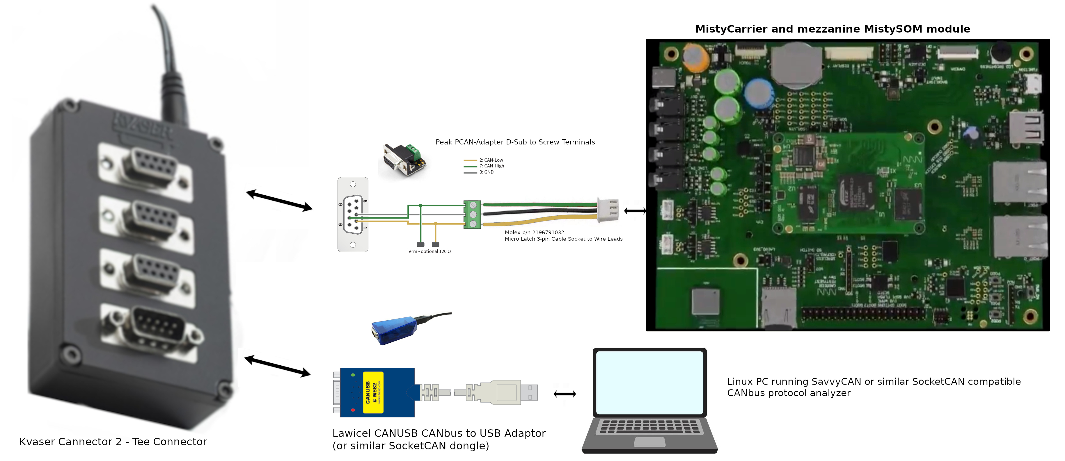 |
|---|
| Fig. 7 - Test Setup for reading and writing to CanBus from MistySOM RZ/G2L |
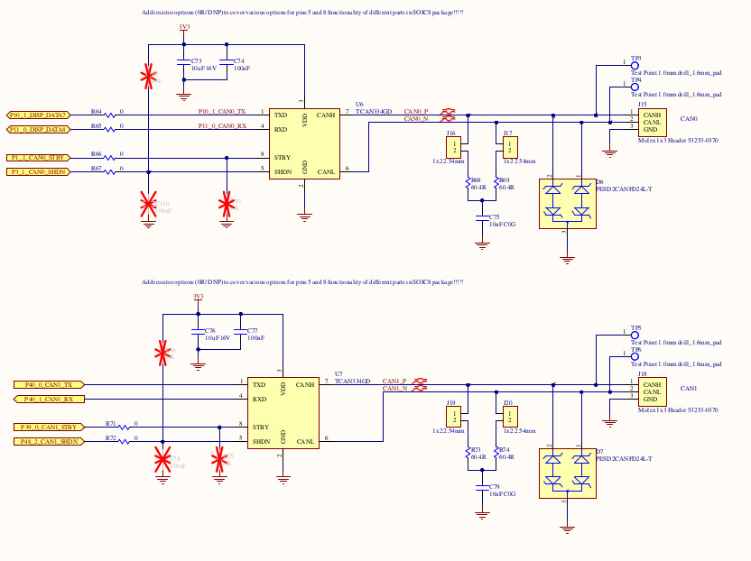 |
|---|
| Fig 8 - MistyCarrier schematic showing CAN0 and CAN2 Molex 1x3 Headers at right. NOTE: Jumpers J16 and J17 (for CAN0 termination) or J19 and J20 (for CAN1 termination) should be installed if the corresponding MistyCAN canbus port is the end of the CAN cable segment. |
Test Procedure Using SocketCAN and iproute2 tools for RZ/G2L and RZ/V2L
Purpose
This article describes how to set up a SocketCAN interface using the iproute2 suite of tools and is included in the RZ/G2L and RZ/V2L SDK.
iproute2 is a set of utilities for Linux networking, including support for SocketCAN interfaces.
Configuring the SocketCAN interface
You can display available network interfaces to find out the available CAN devices:
$ ifconfig -a
can0      Link encap:UNSPEC  HWaddr 00-00-00-00-00-00-00-00-00-00-00-00-00-00-00-00
          NOARP  MTU:16  Metric:1
          RX packets:0 errors:0 dropped:0 overruns:0 frame:0
          TX packets:0 errors:0 dropped:0 overruns:0 carrier:0
          collisions:0 txqueuelen:10
          RX bytes:0 (0.0 B)  TX bytes:0 (0.0 B)
          Interrupt:30

eth0      Link encap:Ethernet  HWaddr 00:80:E1:42:45:EC
.
.
.
Configure the available SocketCAN interface using the ip link command line as follow:
$ ip link set can0 type can bitrate 1000000 dbitrate 2000000 fd on
[ 24.700698] m_can 4400e000.can can0: bitrate error 0.3%
[ 24.704568] m_can 4400e000.can can0: bitrate error 1.6%
To list CAN user-configurable options, use the following command line:
$ ip link set can0 type can help

Usage: ip link set DEVICE type can
        [ bitrate BITRATE [ sample-point SAMPLE-POINT] ] |
        [ tq TQ prop-seg PROP_SEG phase-seg1 PHASE-SEG1
          phase-seg2 PHASE-SEG2 [ sjw SJW ] ]

        [ dbitrate BITRATE [ dsample-point SAMPLE-POINT] ] |
        [ dtq TQ dprop-seg PROP_SEG dphase-seg1 PHASE-SEG1
          dphase-seg2 PHASE-SEG2 [ dsjw SJW ] ]

        [ loopback { on | off } ]
        [ listen-only { on | off } ]
        [ triple-sampling { on | off } ]
        [ one-shot { on | off } ]
        [ berr-reporting { on | off } ]
        [ fd { on | off } ]
        [ fd-non-iso { on | off } ]
        [ presume-ack { on | off } ]

        [ restart-ms TIME-MS ]
        [ restart ]

        Where: BITRATE  := { 1..1000000 }
                  SAMPLE-POINT  := { 0.000..0.999 }
                  TQ            := { NUMBER }
                  PROP-SEG      := { 1..8 }
                  PHASE-SEG1    := { 1..8 }
                  PHASE-SEG2    := { 1..8 }
                  SJW           := { 1..4 }
                  RESTART-MS    := { 0 | NUMBER }

###
Displaying SocketCAN status
To get a detailed status of the SocketCAN link, use the following command line:
$ ip -details link show can0
2: can0: <NOARP,ECHO> mtu 72 qdisc pfifo_fast state DOWN mode DEFAULT group default qlen 10
link/can promiscuity 0
can
Enabling/disabling the SocketCAN interface
Then enable the connection by bringing the SocketCAN interface up:
$ ip link set can0 up
You can check that the interface is up by printing the netlink status:
 $ ip -details link show can0
2: can0: <NOARP,UP,LOWER_UP,ECHO> mtu 72 qdisc pfifo_fast state UNKNOWN mode DEFAULT group default qlen 10
    link/can  promiscuity 0
    can <FD> state ERROR-ACTIVE (berr-counter tx 0 rx 0) restart-ms 0
          bitrate 996078 sample-point 0.745
...
You can disable the connection by bringing the SocketCAN interface down. This command is useful when you need to reconfigure the SocketCAN interface:
$ ip link set can0 down
Loopback test mode
It is possible to configure the SocketCAN in internal Loopback test mode. In that case, the FDCAN treats its own transmitted messages as received messages. This mode can be used for hardware self-test:
$ ip link set can0 type can bitrate 1000000 dbitrate 2000000 fd on loopback on
You can check that the loopback option is on by printing the netlink status:
 $ ip  -details link show can0
2: can0: <NOARP,ECHO> mtu 72 qdisc pfifo_fast state DOWN mode DEFAULT group default qlen 10
    link/can  promiscuity 0
    can <LOOPBACK,FD> state STOPPED (berr-counter tx 0 rx 0) restart-ms 0
          bitrate 996078 sample-point 0.745
CAN Test
Connect Saleae to CANL and bring the device up with the following two instructions:
# ip link set can0 type can bitrate 1000000 dbitrate 2000000 fd on
# ip link set can0 up
then invoke cangen to create example traffic with:
# cangen can0 -D 11223344DEADBEEF -L 8
While cansniffer can be used to monitor incoming traffic:
- for example with a loopback cable to the
can1interface:
# cansniffer can1
or with a connection to can0 on a second board:
# cansniffer can0
Example of SocketCAN interface setup
You can configure and enable the SocketCAN interface in the same command line:
$ ip link set can0 up type can bitrate 1000000 dbitrate 2000000 fd on
[ 24.700698] m_can 4400e000.can can0: bitrate error 0.3%
[ 24.704568] m_can 4400e000.can can0: bitrate error 1.6%
[ 24.710140] IPv6: ADDRCONF(NETDEV_CHANGE): can0: link becomes ready

the repertoire of socketcan commands

root@smarc-rzg2l:~# history
    1  ifconfig -a
    2  ip link set can1 type can bitrate 125000 dbitrate 250000 fd on
    3  ip link set can1 up
    4  ip -details link show can1
    5  cangen can1
    6  ip link set can1 down
    7  ip -details link show can1
    8  ip link set can1 up
    9  cangen can1
   10  ip link set can1 up
   11  ip -details link show can1
   12  ip link set can1 up
   13  ip -details link show can1
   14*
   15  candump can1
   16  which candump
   17  ip -d -s link show can1
   18  ip link set can1 down
   19  ip link set can1 type can bitrate 125000 dbitrate 250000 berr-reporting on fd on
   20  ip link set can1 up
   21  ip -details link show can1
   22  fg
   23  jobs
   24  ip link set can1 down
   25  ip link set can1 up
   26  ip -details link show can1
   27  history
   28  cangen can1
   29  ip -details link show can1
   30  cangen can1 &
   31  ip -details link show can1
   32  ip -d -s link show can1
   33  dmesg -n 7
   34  ip -d -s link show can1
   35  dmesg | less
   36  ip link set can1 down
   37  ip link set can1 downjobs
   38  jobs
   39  ip link set can1 type can bitrate 125000 dbitrate 4000000 berr-reporting on fd off
   40  ip link set can1 type can bitrate 125000 berr-reporting on fd off
   41 ip link set can1 type can bitrate 125000 berr-reporting on fd on
   42  ip link set can1 type can bitrate 125000 berr-reporting on
   43  ip link set can1 down
   44  ip -d -s link show can1
   45  ip link set can1 type can bitrate 125000
   46  ip -d -s link show can1
   47  cangen can1 &
   48  ip link set can1 up
   49  cangen can1 &
   50  ip -d -s link show can1
   51  ip link set can1 type can bitrate 125000 berr-reporting on
   52  jobs
   53  fg 1
   54  ip link set can1 down
   55  ip link set can1 type can bitrate 125000 berr-reporting on
   56  ip link set can1 up
   57  cangen can1
   58  candump can1
   59  ip -d -s link show can1
   60  ip link -help
   61  ip link help
   62  candump -h
   63  candump -c -c -x -e -ta can1
   64  canfdtest
   65  canfdtest -vv can1
   66  canfdtest
   67  canfdtest -g -vv can1
   68  tmux
   69  cangen can1 &
   70  candump can1
   71  jobs
   72  fg 1
   73  canbusload can1
   74  canbusload can1@125000 -r -t -b -c
   75  canbusload
   76  canbusload can1@125000 -r -t -b -c -e
   77  ip -d -s link show can1
   78  history
Troubleshooting & FAQ
error experienced:
ifconfig can0 txqueuelen 1000
can be resolved with:
# ifconfig can0 txqueuelen 1000
This will increase the number of frames allowed per kernel transmission queue for the queuing discipline. More info here
Design Files
MistySOM
MistyCarrier
Documentation
Block Diagrams
Additional design files are available upon request: mistysom@mistywest.com
